TM 5-814-3/AFM 88-11, Volume III
c. Discussion The text states that for proper operation of a proportional weir, complete free-flow
conditions must exist below the weir crest. Therefore, in this case, the depth of the effluent channel below
the weir crest would have to be 1.5 ft, the maximum liquid depth in the effluent channel. With a Parshall
flume (according to the text), the permissible submergence is 65 percent of Ha or, in this case, 0.65 1.38
= 0.9 ft. The effluent channel floor would have to be 1.5 - 0.9 = 0.6 ft below the floor of the approach to the
Parshall flume. For a Venturi flume (according to the text), the head loss to be provided for should not be
less than H/3 or, in this case, 2.35/3 = 0.78 ft. The crest could, therefore, be submerged 2.0-0.78 = 1.22 ft
and the effluent channel floor could be 1.5-1.22 = 0.28 ft below the crest. However, to satisfy the design with
respect to d, the depth of the effluent channel would have to be 0.35 ft below the crest. The foregoing
analysis indicates that the three devices would require head losses of 1.5, 0.60 and 0.35 ft, respectively.
Consideration of these losses and local conditions would determine which of the three designs should be used.
C-2. Mechanical flocculation. (Refer to para 10-6b.)
a. Design requirements and criteria. Design a mechanical flocculator as a part of chemical precipitation
to handle a flow rate of 4 mgd. The following conditions apply:
Temperature = 20EC (68Ef);
Paddle-tip speed = 1.2 fps;
Coefficient of drag of paddles = 1.8.
b. Calculations and results.
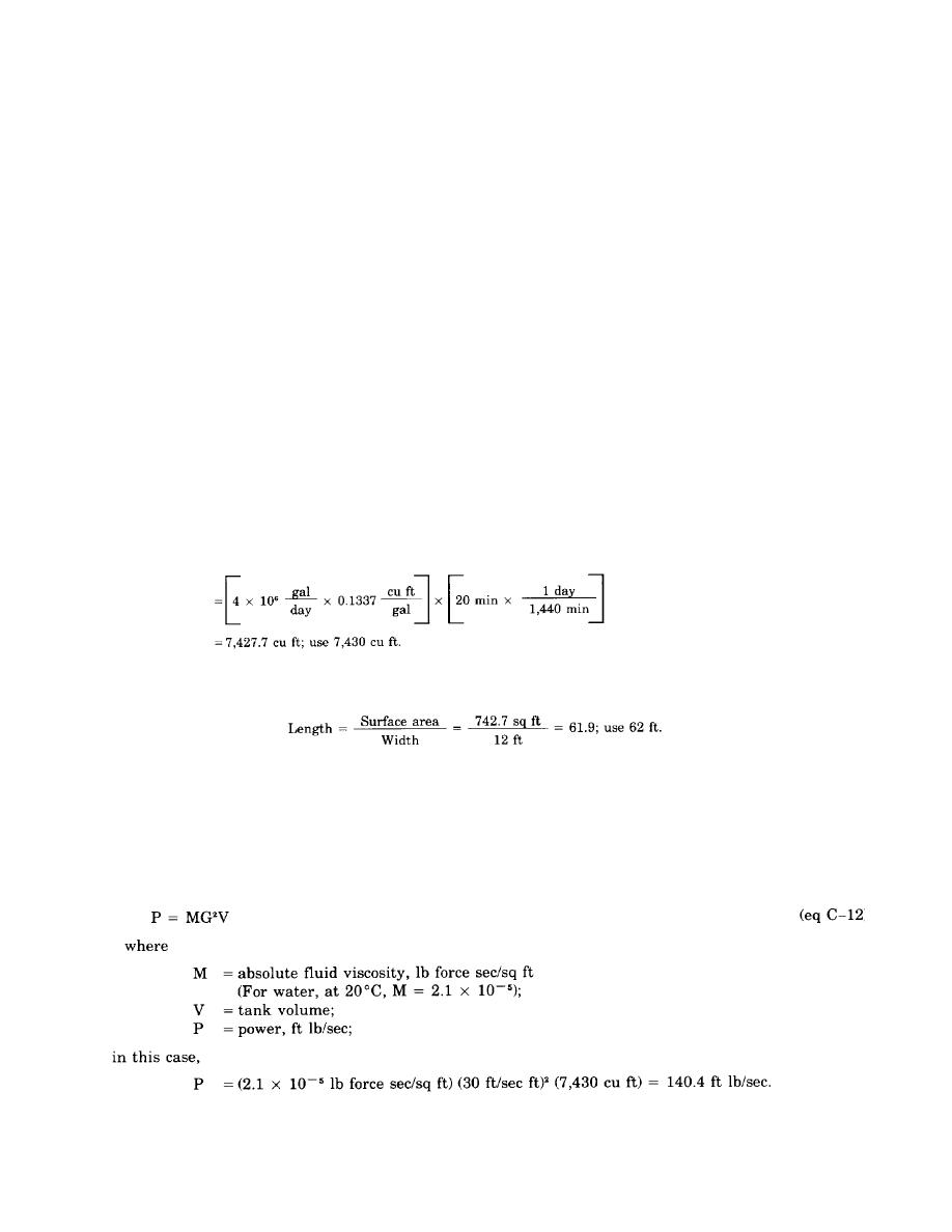
(1) Using a detention time of 20 minutes, determine tank volume.
Volume = flow rate detention time
(2) Using a depth of 10 ft, determine tank dimensions. Width is usually set by standard sludge removal
equipment sizes. A width of 12 ft will be used here.
A tank size of 12 ft 62 ft would be appropriate here and would produce a satisfactory length-to-width ratio
of about 5.4:1.
(3) A major design factor in flocculator design is mean velocity gradient (G), measured in ft/sec ft. A
typical value of 30 ft/sec ft will be used in this case.
(4) The theoretical power requirement is calculated by using the following formula (derived from para
10-6c):
C-14


 Previous Page
