TM 5-814-3/AFM 88-11, Volume III
Again making use of Q = Av,
V = 10.829/4.70 = 2.3 fps;
therefore,
= 0.222 (32 - 2.32)
h
= 0.222 3.7
= 0.082 ft, or approximately 1 inch.
If the screen is half plugged with screening, leaves and other debris:
From Q = Av, the area is directly proportional to the velocity. In other words, if the area is cut in half, the
velocity must double. The head loss, therefore, is:
= 0.222 (62 - 2.32)
h
= 0.222 30.7
= 0.682 ft, or approximately 8 inches.
The increase in head loss is over one-half foot as the screen becomes half plugged. The need for accurate
control of the cleaning cycle and protection against surge loads is thus demonstrated.
(4) Parshall flume. From inspection of table C-13, it is readily obvious that by using two grit channels
with bottom width of 0.75 ft and with sides sloping at an angle whose cotangent is 0.67, a Parshall flume with
a throat width of 0.75 ft would control the velocity within the specified limits. The table of discharge for
Parshall flumes (table C-2) indicates that for flows of 0.67, 1.67 and 5.0 cfs, the values of Ha are 0.34, 0.67
and 1.38, respectively. By appropriate substitution in equation C-4, the corresponding velocities are found
to be 0.91, 1.04 and 1.08 fps.
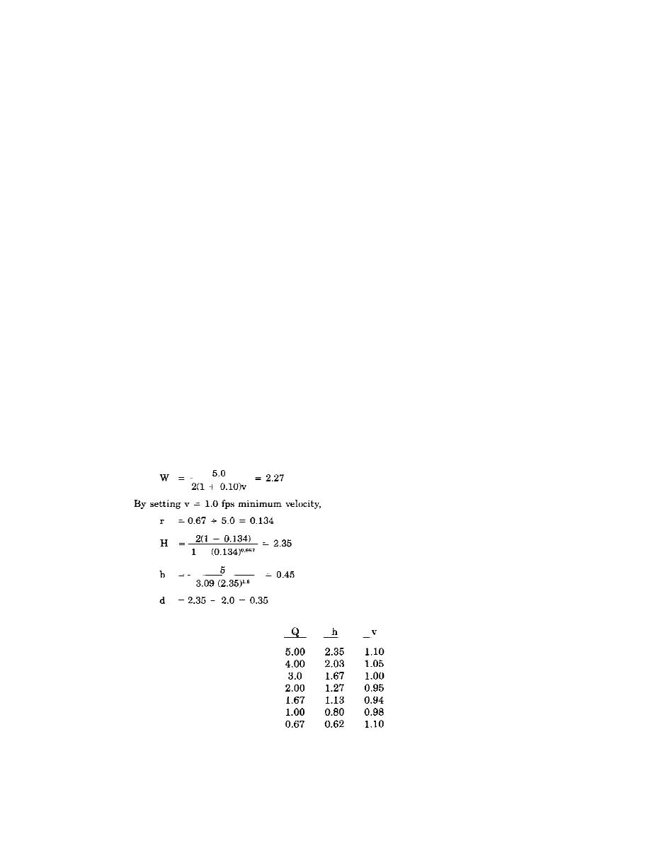
(5) Venturi flume. In this case, design for D = 2.0. Then W, H, b and d are determined by substituting
(in eqs C-S through C-8, respectively) as follows:
For various values of Q, the values of h and v (determined from eqs C-9 and C-10) are as follows:
This tabulation indicates that for values of Q varying between 0.67 cfs and 5.0 cfs, the velocity in the grit
chamber would not vary more than 10 percent from 1.0 fps and that the design would be satisfactory in this
respect.
C-13


 Previous Page
