TM 5-818-5/AFM 88-5, Chap 6/NAVFAC P-418
Table 4-2. Capacity of Various Size Submersible and Deep- Well Turbine Pumps
Approximate
Maximum Capacity
Maximum Pump
Inside Diameter
gallons per minute
Bowl or Motor Size
of Well
Submersible
inches
Deep Well
inches
4
70
5-6
90
--
5
6-8
160
250
6
8-10
450
400
8
10-12
600
10
700
1,200
12-14
1,100
12
14-16
1,800
--
14
2,400
16-18
--
16
3,000
18-20
U. S. Army Corps of Engineers
screen and riser pipe, total pumping head, and the low-
ered elevation of the water in the well. The diameter of
the pump bowl must be determined before the wells
are installed, as the inside diameter of the well casing
should be at least 3 to 4 inches larger in diameter than
the pump bowl. Approximate capacities of various tur-
bine pumps are presented in table 4-2. The character-
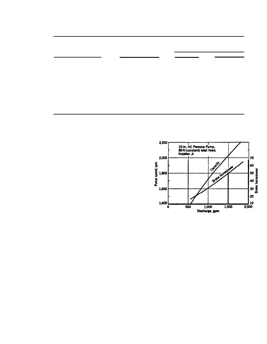
istics of a typical three-stage, lo-inch turbine pump
are shown in figure 4-35.
(3) Submersible pumps require either electric
power from a commercial source or one or more motor
generators. If commercial power is used, 75 to 100 per-
cent of (connected) motor generator power, with auto-
matic starters unless operational personnel are on
duty at all times, should be provided as standby for the
commercial power. Spare submersible pumps, general-
(Courtesy of Fairbanks Morse, Inc., Pump Division)
ly 10 to 20 percent of the number of operating pumps,
Figure 4-35. Rating curves for a three-stage 10-inch-high capacity
as well as spare starters, switches, heaters, and fuses,
deep-wellpump.
should also be kept at the site.
(4) Deep-well turbine pumps can be powered with
to connect the header pipe to a 30- or 36-inch collec-
either electric motors or diesel engines and gear
tion tank about 20 or 30 feet deep, sealed at the bot-
drives. Where electric motors are used, 50 to 100 per-
tom and top, and pump the flow into the tank with a
cent of the pumps should be equipped with combina-
high-capacity deepwell turbine pump using a separate
tion gear drives connected to diesel (standby) engines.
vacuum pump connected to the top of the tank to pro-
The number of pumps so equipped would depend upon
duce the necessary vacuum in the header pipe for the
the criticality of the dewatering or pressure relief
wells or wellpoints.
needs. Motor generators may also be used as standby
d. Header pipe.
for commercial power. For some excavations and sub-
(1) Hydraulic head losses caused by flow through
surface conditions, automatic starters may be required
the header pipe, reducers, tees, fittings, and valves
for the diesel engines or motor generators being used
should be computed and kept to a minimum (1 to 3
as backup for commercial power.
feet) by using large enough pipe. These losses can be
computed from equivalent pipe lengths for various fit-
c. Turbovacuum pumps. For some wellpoint sys-
tings and curves.
tems requiring high pumping rates, it may be desirable
4-39


 Previous Page
