TM 5-815-5/AFM 88-5, Chap 6/NAVFAC P-418
from 4 to 18 inches with a screen 20 to 75 feet long de-
4-5. Numerical analyses.
pending on the flow and pump size requirements.
a. Many complex seepage problems, including such
(1) Well screens. Screens generally used for de-
categories as steady confined, steady unconfined, and
watering wells are slotted (or perforated) steel pipe,
transient unconfined can be solved using the finite ele-
perforated steel pipe wrapped with galvanized wire,
ment method. Various computer codes are available at
galvanized wire wrapped and welded to longitudinal
the WES and the NAVFAC program library to handle
rods, and slotted polyvinyl chloride (PVC) pipe. Riser
a variety of two- and three-dimensional seepage prob-
pipes for most dewatering wells consist of steel or PVC
lems. The codes can handle most cases of nonhomoge-
pipe. Screens and riser for permanent wells are usually
neous and anisotropic media.
made of stainless steel or PVC. Good practice dictates
b. A general computer code for analyzing partially
the use of a filter around dewatering wells, which per-
penetrating random well arrays has been developed
mits the use of fairly large slots or perforations, usual-
based on results of three-dimensional electrical anal-
ly 0.025 to 0.100 inch in size. The slots in well screens
ogy model tests at the WES. The computer code pro-
should be as wide as possible but should meet criteria
vides a means for rapidly analyzing trial well systems
given in c below.
in which the number of wells and their geometric con-
(2) Open screen area. The open area of a well
figuration can be varied to determine quantities of
screen should be sufficient to keep the entrance veloc-
seepage and head distributions. Wells of different
ity for the design flow low to reduce head losses and to
radii and penetrations can be considered in the analy-
minimize incrustation of the well screen in certain
sis.
types of water. For temporary dewatering wells in-
stalled in nonincrusting groundwater, the entrance ve-
4-6. Wellpoints, wells, and filters. Wells
locity should not exceed about 0.15 to 0.20 foot per
and wellpoints should be of a type that will prevent in-
second; for incrusting groundwater, the entrance ve-
filtration of filter material or foundation sand, offer
locity should not exceed 0.10 to 0.20 foot per second.
little resistance to the inflow of water, and resist cor-
For permanent drainage wells, the entrance velocity
rosion by water and soil. Wellpoints must also have
should not exceed about 0.10 foot per second. As the
sufficient penetration of the principal water-carrying
flow to and length of a well screen is usually dictated
strata to intercept seepage without excessive residual
by the characteristics of the aquifer and drawdown re-
head between the wells or within the dewatered area.
quirements, the required open screen area can be ob-
tained by using a screen of appropriate diameter with
a. Wellpoints. Where large flows are anticipated, a
a maximum amount of open screen area.
high-capacity type of wellpoint should be selected. The
(3) Well hydraulics. Head losses within the well
inner suction pipe of self-jetting wellpoints should per-
system discussed in paragraph 4-2a(5) can be esti-
mit inflow of water with a minimum hydraulic head
mated from figure 4-24.
loss. Self-jetting wellpoints should be designed so that
most of the jet water will go out the tip of the point,
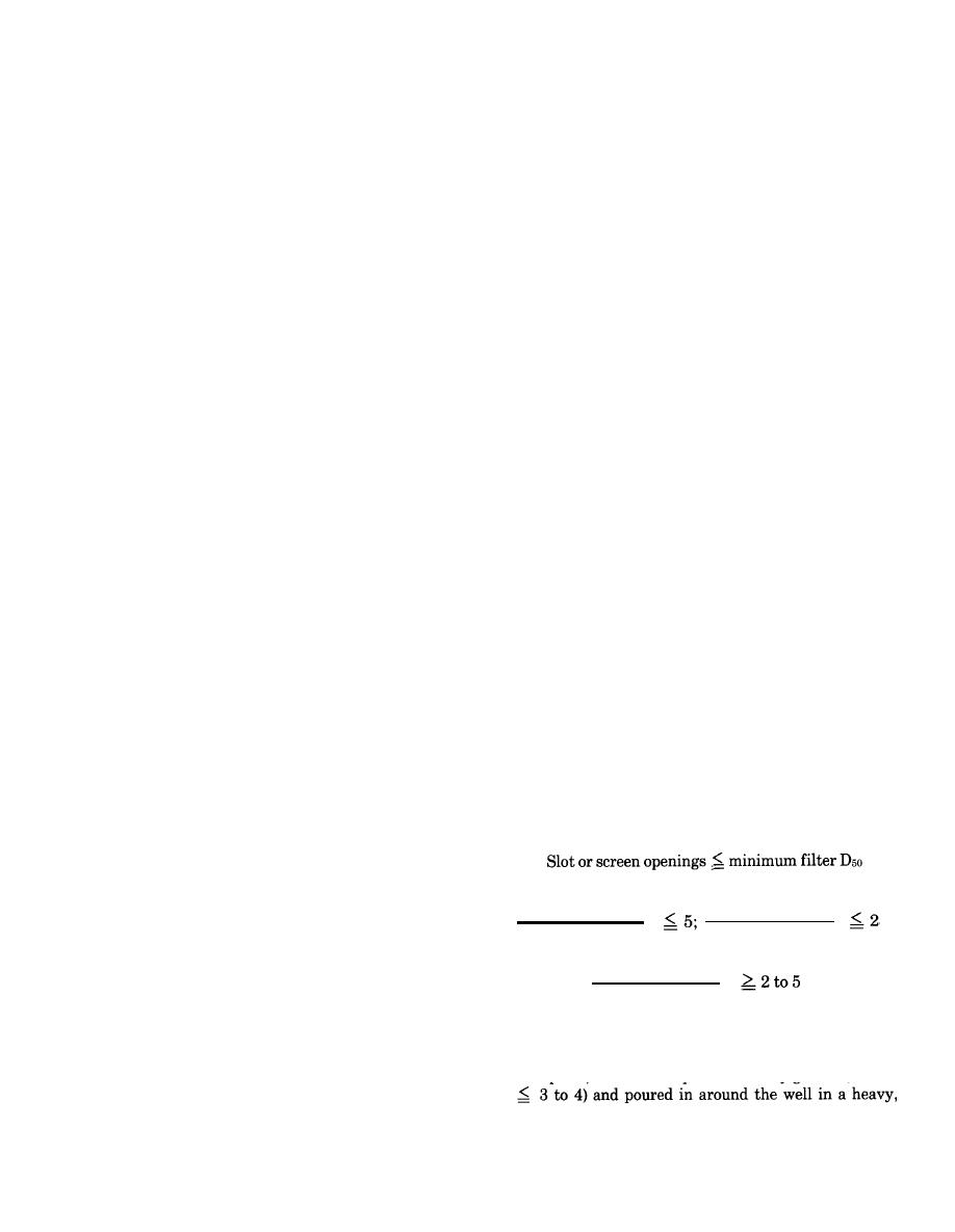
c. Filters. Filters are usually 3 to 5 inches thick for
with some backflow to keep the screen flushed clean
wellpoints and 6 to 8 inches thick for large-diameter
while jetting the wellpoint in place.
wells (fig. 4-30). To prevent infiltration of the aquifer
(1) Wellpoint screens. Generally, wellpoints are
materials into the filter and of filter materials into the
covered with 30- to 60-mesh screen or have an equiva-
well or wellpoint, without excessive head losses, filters
lent slot opening (0.010 to 0.025 inch). The mesh
should meet the following criteria:
should meet filter criteria given in c below. Where the
Screen-filter criteria
soil to be drained is silty or fine sand, the yield of the
wellpoint and its efficiency can be greatly improved by
placing a relatively uniform, medium sand filter
Filter-aquifer criteria
around the wellpoint. The filter should be designed in
Max filter D50
Max filter D15
accordance with criteria subsequently set forth in c be-
Min aquifer D50
Min aquifer D85
low. A filter will permit the use of screens or slots with
larger openings and provide a more pervious material
Min filter D15
around the wellpoint, thereby increasing its effective
radius (d below).
Max aquifer D15
(2) Wellpoint hydraulics. The hydraulic head
If the filter is to be tremied in around the screen for a
losses in a wellpoint system must be considered in de-
well or wellpoint, it may be either uniformly or rather
signing a dewatering system. These losses can be esti-
widely graded; however, if the filter is not tremied
mated from figure 4-25.
into place, it should be quite uniformly graded (D90/D10
b. Wells. Wells for temporary dewatering and per-
continuous stream to minimize segregation.
4-34


 Previous Page
