TM 5-818-5/AFM 88-5, Chap 6/NAVFAC P-418
(2) Wellpoint header pipes should be installed as
close as practical to the prevailing groundwater eleva-
tion and in accessible locations. Wellpoint pumps
should be centrally located so that head losses to the
ends of the system are balanced and as low as possible.
If suction lift is critical, the pump should be placed low
enough so that the pump suction is level with the
header, thereby achieving a maximum vacuum in the
header and the wellpoints. If construction is to be per-
formed in stages, sufficient valves should be provided
in the header to permit addition or removal of portions
of the system without interrupting operation of the re-
mainder of the system. Valves should also be located
to permit isolation of a portion of the system in case
In stratified subsurface soils, such as a course-grained
construction operations should break a swing connec-
pervious stratum overlain by a finer grained stratum
tion or rupture a header.
of relatively low permeability, most of the head loss
(3) Discharge lines should be sized so that the
through the entire section would probably occur.
head losses do not create excessive back pressure on
through the finer grained material. Consequently, a
the pump. Ditches may be used to carry the water
factor of safety based on the head loss through the top
from the construction site, but they should be located
stratum would probably indicate a more critical condi-
well back of the excavation and should be reasonably
tion than if the factor of safety was computed from the
watertight.
total head loss through the entire section. Also, when
gradients in anisotropic soils are determined from
4-8. Factors of safety.
flow nets, the distance over which the head is lost
a. General. The stability of soil in areas of seepage
must be obtained from the true section rather than the
emergence is critical in the control of seepage. The exit
transformed section.
gradient at the toe of a slope or in the bottom of an ex-
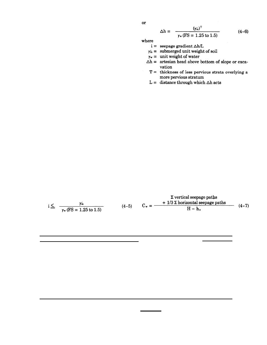
c. Piping. Piping cannot be analyzed by any rational
cavation must not exceed that which will cause surface
method. In a study of piping beneath hydraulic struc-
raveling or sloughing of the slope, piping, or heave of
tures founded on granular soils, it was recommended
the bottom of the excavation.
b. Uplift. Before attempting to control seepage, an
ceed the values shown in table 4-3 for various types of
analysisshould be made to ensure that the seepage or
granular soils.
uplift gradient is equal to or less than that computed
from the following equations:
Table 4-3. Minimum Creep Ratios for Various Granular Soils
Creep Ratio
Soil
V e r y fine sand or silt
8.5
Fine sand
7
Medium sand
6
Coarse sand
5
Fine gravel
4
Medium gravel
3.5
Coarse gravel including cobbles
3
Boulders with some cobbles and gravel
2.5
From "Security from Under-Seepage Masonry Dams, "by E. W. Lone, pp. 1235-1272.
Transactions, American Society of Civil Engineers, 1935.
4-40


 Previous Page
