TM 5-818-5/AFM 88-5, Chap 6/NAVFAC P-418
(4) For gravity flow, equipotential lines intersect
or
the phreatic surface at equal intervals of elevation,
(4-2a)
each interval being a constant fraction of the total net
with
head.
=
c. Flow nets are limited to analysis in two dimen-
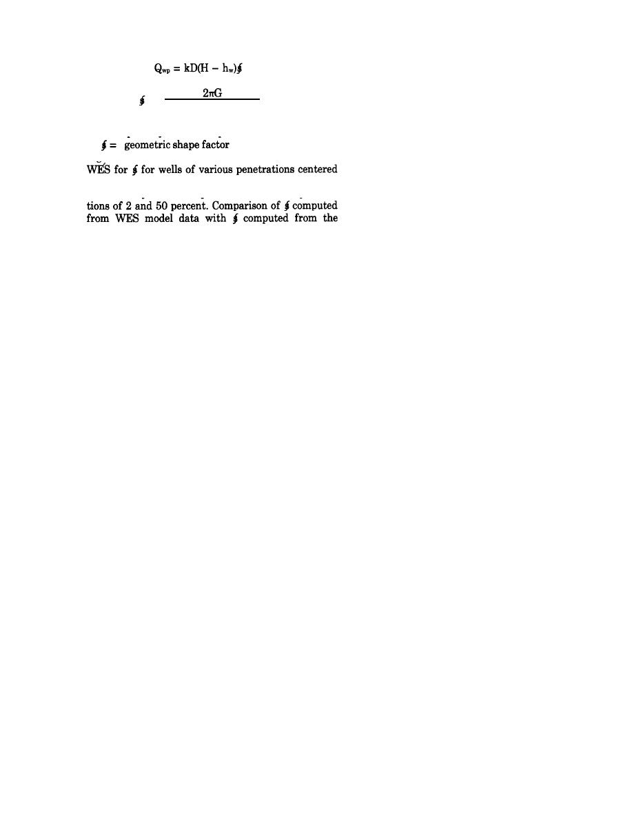
1n(Rrw)
sions; the third dimension in each case is assumed in-
where
finite in extent. An example of a sectional flow net
G = quantity shown in equation (6), figure 4-10
showing artesian flow from two line sources to a par-
tially penetrating drainage slot is given in figure
Figure 4-26 shows some of the results obtained at the
4-27a. An example of a plan flow net showing artesian
flow from a river to a line of relief wells is shown in
inside a circular source. Also presented in figure 4-26
figure 4-27b.
are boundary curves computed for well-screen penetra-
d. The flow per unit length (for sectional flow nets)
or depth (for plan flow nets) can be computed by
boundary formulas indicates fairly good agreement for
means of equations (1) and (2) and (5) and (6) respec-
well penetrations > 25 percent and values of R/D be-
tively (fig. 4-27). Drawdowns from either sectional or
tween about 5 and 15 where R/rw > 200 to 1000.
plan flow nets can be computed from equations (3) and
Other empirical formulas for flow from a partially
(4) (fig. 4-27). In plan flow nets for artesian flow, the
netrating well suffer from the same limitations.
equipotential lines correspond to various values of H-
(4) Partially penetrating wells. The equations for
h, whereas for gravity flow, they correspond to H2-h2.
gravity flow to partially penetrating wells are only
Since section equipotential lines for gravity flow con-
considered valid for relatively high-percent penetra-
ditions are curved rather than vertical, plan flow nets
tions.
for gravity flow conditions give erroneous results for
large drawdowns and should always be used with cau-
4-3. Flow-net analyses.
tion.
a. Flow nets are valuable where irregular configura-
e. Plan flow nets give erroneous results if used to
tions of the source of seepage or of the dewatering sys-
analyze partially penetrating drainage systems, the er-
tem make mathematical analyses complex or impossi-
ror being inversely proportional to the percentage of
ble. However, considerable practice in drawing and
penetration. They give fairly accurate results if the
studying good flow nets is required before accurate
penetration of the drainage system exceeds 80 percent
flow nets can be constructed.
and if the heads are adjusted as described in the fol-
b. A flow net is a graphical representation of flow of
lowing paragraph.
water through an aquifer and defines paths of seepage
f. In previous analyses of well systems by means of
(flow lines) and contours of equal piezometric head
flow nets, it was assumed that dewatering or drainage
(equipotential lines). A flow net may be constructed to
wells were spaced sufficiently close to be simulated by
represent either a plan or a section view of a seepage
a continuous drainage slot and that the drawdown
pattern. Before a sectional flow net can be con-
(H-hD) required to dewater an area equaled the aver-
structed, boundary conditions affecting the flow pat-
age drawdown at the drainage slot or in the lines of
tern must be delineated and the pervious formation
wells (H-h,). These analyses give the amount of flow
transformed into one where kn = kv (app E). In draw-
QT that must be pumped to achieve H-hD but do not
ing a flow net, the following general rules must be ob-
give the drawdown at the wells. The drawdown at the
served:
wells required to produce H-ho downstream or within
(1) Flow lines and equipotential lines intersect at
a ring of wells can be computed (approximately) for ar-
right angles and form curvilinear squares or rec-
tesian flow from plan flow nets by the equations
tangles.
shown in figure 4-28 if the wells have been spaced
(2) The flow between any two adjacent flow lines
proportional to the flow lines as shown in figure 4-27.
and the head loss between any two adjacent equipoten-
The drawdown at fully penetrating gravity wells can
tial lines are equal, except where the plan or section
also be computed from equations given in figure 4-28.
cannot be divided conveniently into squares, in which
case a row of rectangles will remain with the ratio of
4-4. Electrical analogy seepage models.
the lengths to the sides being constant.
a. The laws governing flow of fluids through porous
(3) A drainage surface exposed to air is neither an
media and flow of electricity through pure resistance
equipotential nor flow line, and the squares at this sur-
are mathematically similar. Thus, it is feasible to use
face are incomplete; the flow and equipotential lines
electrical models to study seepage flows and pressure
need not intersect such a boundary at right angles.
4-29


 Previous Page
