EI 02C097
01 Jul 97
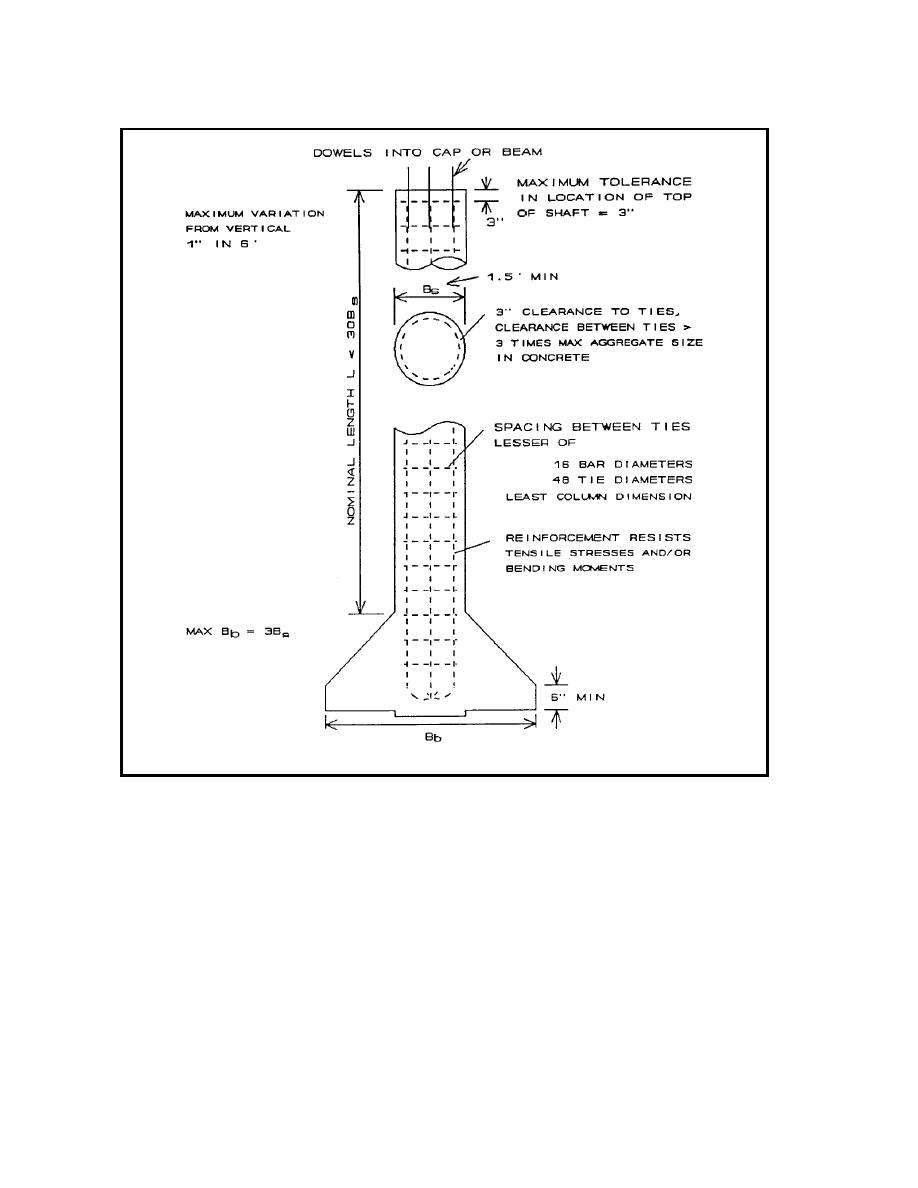
Figure 1-4. Drilled shaft details (1 in. = 25.4 mm)
(2) Skin resistan e mobilization. Full skin resistance is typically mobilized
c
length/diameter ratios less than 10. The selected shaft dimension
s
within 0.5 inch of displacement, while end bearing may not be fully mobilize
d
should minimize the volume of concrete required and maximie
z
until displacements ex eed 10 to 20 percent of the base diameter or underream for
c
constuction efficiency. T e lateral load capacity of driven piles may be
h
drilledshafts, unless the tip is supported by stiff clay, dense sand, or rock. Figure
increased
by
increasing
the
number
of
pile
s
1-5 illustrates an example of the vertical axial load displacement behavior oa
f
single pile or drilled shaf. The load-displacement behavior and displacements that
t
correspond to ultimateload are site specific and depend on the results of analyses.
These analyses are given in Chapter 3.
(3) Lateral loads. Lateral load capacity of a pile or drilled shaft is directly
related to the diameter, thus increasing the diameter increases the load-carryin
g
capacity. For a drilled shaft that sustains no axial load, the cost of constructio
n
may be optimized by theselection of rigid shaftswithout underreams and with
1-9


 Previous Page
