TM 5-809-3/NAVFAC DM-2.9/AFM 88-3, Chap. 3
Note: Steel governed the design. Also, note Mrm and Mrs could have been taken from appendix C, table C-9.
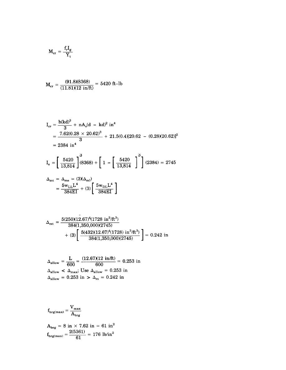
Deflection Check
fr = 2.54%f*m = 2.5%1350 lb/in2 = 91.8 lb/in2
Where:
Ig = (7.62)(23.62)3/12 = 8368 in4
Yt = 23.62/2 = 11.81 in
Since Mcr < Mmax; the lintel is cracked, therefore the effective moment of inertia, Ie, must be computed as
follows:
Ie = (Mcr/Mmax)3Ig + [1 - (Mcr/Mmax)3] Icr
Where:
Icr = The moment of inertia of the cracked section, in4
Note. Icr could be taken from table C-9.
(b) Determine the lintel deflection, mt, as follows:
Since the line of action of the concentrated load is located off the lintel span and the vertical height of the
distribution triangle is only 2 feet, the effects of the concentrated load on the centerline deflection is negligible
and will be ignored.
(c) Determine the allowable lintel deflection, )allow, and compare to the maximum lintel deflection,
)max = 0.30 in, as follows:
...Deflection O.K.
Bearing Check.
(a) Determine the maximum bearing stress, f brg(max), assuming a triangular stress distribution as
follows:
Where:
(b) Determine the allowable bearing stress, Fbrg, as follows:
8-9


 Previous Page
