TM 5-809-3/NAVFAC DM-2.9/AFM 88-3, Chap. 3
Fmkjbd 2
Mrm '
(ft&lb)
(eq 5-15)
2(12)
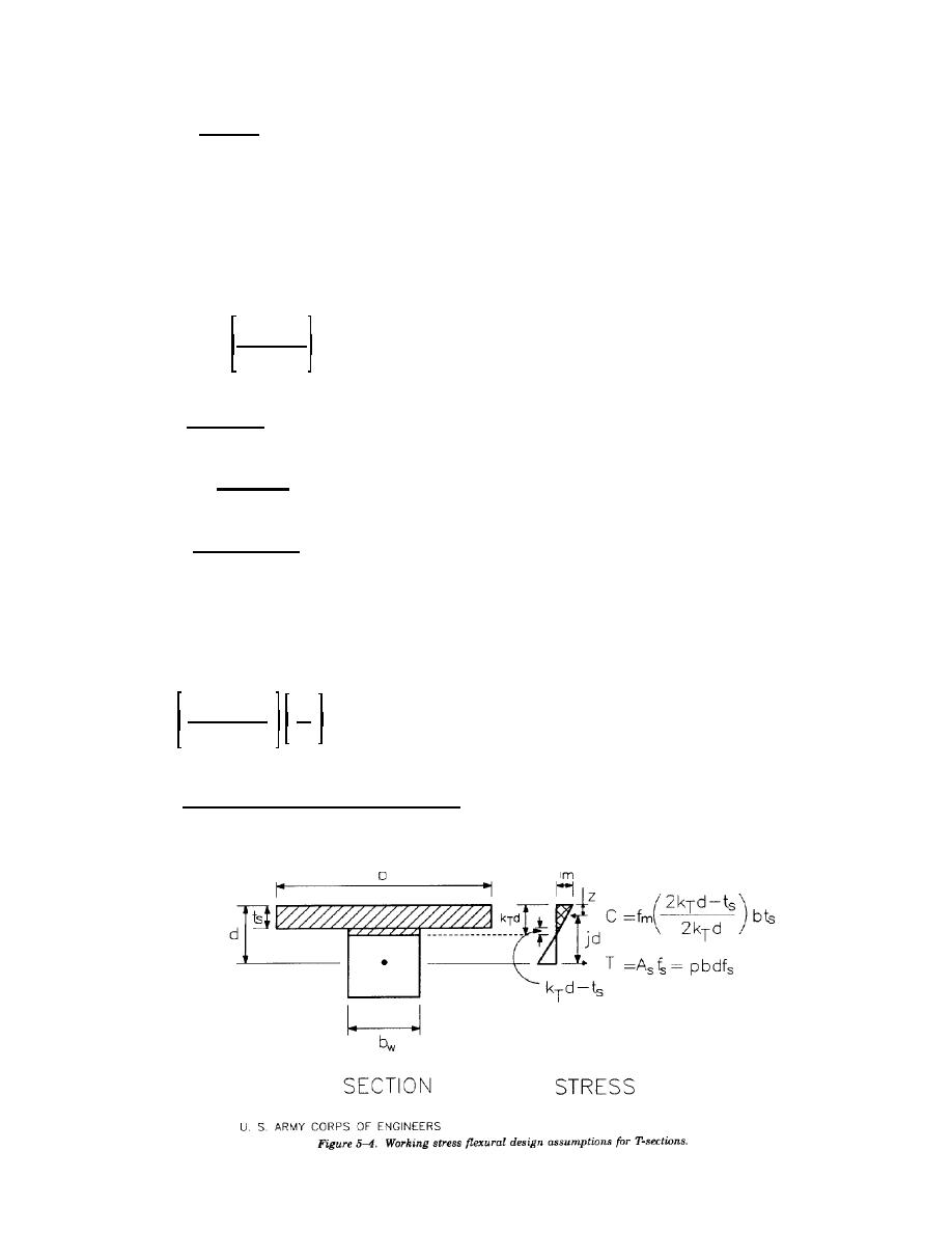
b. Flexural design T-sections. The coefficients and cross section geometry used in the derivation of the
flexural design equations for T-sections are illustrated in figure 5-4.
(1) Design coefficients. In the design of reinforced T-sections, as in the design of rectangular sections,
the first step is to locate the neutral axis. As with rectangular sections, this can be accomplished by
determining the coefficient kT. kT is derived by assuming that the compressive force in the flange, C, is equal
to the tension force in the reinforcement. The contribution of the portion of the web in compression is small
and can be neglected, therefore if;
T.C
Then,
2kTd & ts
pbdfs ' fm
bts
(eq 5-16)
2kTd
Where:
ts = The thickness of the face shell of the unit, inches.
From the strain compatibility relationship it can be determined that;
n
kT '
n % (fs/fm)
Rearranging the equation and solving for fm yields:
kT
fm ' (fs)
n(1 & kT)
Substituting this equation for fm into equation 5-16 yields;
2
np % 1/2(ts/d)
kT '
(eq 5-17)
np % (ts/d)
The coefficient, jT, can be determined by the relationship,
jTd = d - z
Where:
z = The distance from the extreme compressive fiber to the center of compression (or the center
of gravity of the trapezoid shown in figure 5-4) and is determined as follows:
3kTd & 2ts
ts
z'
2kTd & ts
3
From the above equations jT can be determined by:
6 & 6(ts/d) % 2(ts/d)2 % (ts/d)3[1/(2pn)]
jT '
(eq 5-18)
6 & 3(ts/d)
The resisting moments of the steel and masonry are equal to the product of the moment arm, jTd, and the
tension or compression force, respectively, therefore:
5-7


 Previous Page
