(Fp ) min = 0.3(1.125)1.5(576 - lb) = 292 - lb < 467 - lb = Fp (1.30KN < 2.04KN)
O.K.
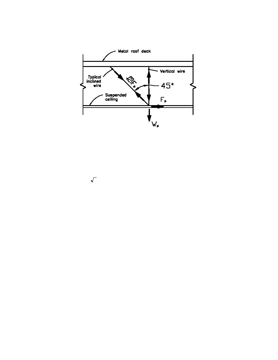
Figure I1-1. Force diagram for bracing wires
F.2 Design members.
Inclined wires;
Tension in inclined wire = 2Fp = 660 - lb (2.94KN)
(see Figure I1-1)
Since only lateral loads are acting in the inclined wires all load combinations reduce to;
Qu = 1.0E = 1.0Fp = 660-lb
(2.94KN)
(ANSI/ASCE 7-95)
Use #10 galvanized soft steel wire (ASTM A651)
fu = 70ksi (482.7MPa)
fy = 50ksi (344.8MPa)
(assumed)
use fallow = fy = 50ksi (344.8MPa)
As = 0.0143-in2 (9.23mm2)
fs = Qu/As = 660-lb/0.0143-in2 = 46.2ksi < 50ksi = fallow
O.K.
(318.5MPa < 344.8MPa)
Vertical wires;
Dead load on the wire was previously calculated as Wp = 576-lb (2.56KN). The ability of the dead load to
keep the wire taught is to be checked.
O.K.
Qu = 0.9D + 1.0QE = 0.9(-576-lb) + 467-lb = -51-lb-tension (0.23KN)
Connections;
A L2X2X3/16X1' 3" (L50.8mmX50.8mmX4.8mmX0.38m) angle is used to transfer load to the steel deck.
-
Angle is to be welded to at least two flutes of the deck as shown in Figure I1-2. The worst case loading is
due to gravity load effects acting alone and was calculated as Pu = 806-lb (3.59MN). It is decided to weld
to each flute using 2-in. by 1/8-in. (50.8mmX3.2mm) fillet welds as shown (total weld length is 8-in.
(203.2mm)).
I1-3


 Previous Page
