Width-to-Thickness Ratio: (Section 14.2.d)
D/t ≤1300/Fy = 1300/36 = 36.11 (AISC Seismic Provisions Table I-9-1)
D/t = 4.5 / 0.337 = 13.4 < 36.11, OK
(e) Moment frames:
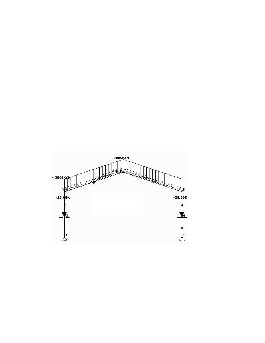
The moment frames resist seismic forces from the upper roof diaphragm and are braced by the lower
sloped diaphragms (by horizontal bracing). The frames also support gravity loads from the upper roof
and from the beam reactions along grid lines B & H.
Gravity:
Dead = 218 plf (3.18 KN/m)
Live = 238 plf (3.47 KN/m)
Beam reactions = 23.9 k (106.3 KN)
Seismic:
Vupper roof =4.81 k (21.4 KN)
The members of the moment frames have already been checked for the gravity load combination and
now are checked for the seismic load combination: 1.2D + 0.5L + 1.0E where E = ρQE + 0. The
vertical seismic effects are captured by the term 0.2 SDSD = 0.2(1.0) = 0.2D. This term is added to the
1.2D load term to a total of 1.4D for this load combination.
Loads for elastic analysis: It is assumed that the lateral load to the upper portion of the frames is
applied at the top middle node.
1 kip = 4.448 KN
1 K/ft = 14.59 KN/m
Beam Design:
The elastic analysis results show that the maximum moment (84.0 kft) and axial force in the beam (15.1
k) are lower than those for the load combination of 1.2D + 1.6L. By inspection it is seen that the beams
are adequate.
Column Design:
Top portion: φPn = 802 k (3567 KN) φMn = 518 kipft (702 KNm)
c
b
Bottom portion: φPn = 927 k (4123 KN) φMn = 518 kipft (702 KNm)
c
b
For the upper portion of the column (above the horizontal bracing level) the maximum axial force = 13.2k
(58.7 KN) and the moment is 84.0 kipft (114 KNm). For the lower portion of the columns the maximum
axial force is 41.84 kips (186 KN) and the moment is 70.6 kipft (95.7 KNm). The columns are seen to be
adequate by inspection.
H3-49


 Previous Page
