B-5 Perform Static Analysis
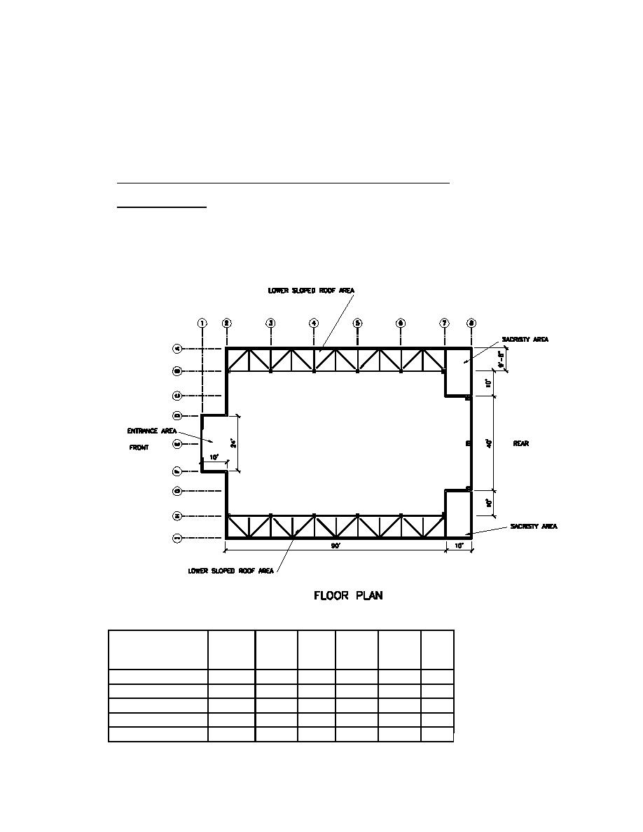
The seismic forces from the upper sloped roof and entrance are resisted by the vertical elements based on
tributary areas due to flexible diaphragm action. The seismic forces tributary to the sacristies and lower
sloped roof areas are resisted by the vertical elements based on relative rigidity due to rigid diaphragm
action.
Seismic forces to vertical resisting elements from upper sloped roof diaphragm
Transverse direction: Seismic forces tributary to the sloped upper roof in the transverse direction are
resisted by the steel moment frames and the concrete shear walls based on tributary areas. It is assumed
that the frames along grid lines 2 and 7 resist no loads due to their low stiffness as compared to the shear
walls along the same grid lines. The diaphragm forces are determined from the weight of the roof and
tributary normal walls. It is assumed that the diaphragm acts as a simply supported beam element between
the frames and shear walls.
1 inch = 25.4mm
1 foot = 0.305m
Weight of roof and normal walls between grid lines 2 and 7
Item
Tributary
Length /
% Solid
Area
Unit
Seismic
Height /
Width
(ft.2)
Weight
Weight
Width
(ft.)
(psf / lb)
(kips)
(ft.)
UPPER ROOF
Roof (grid 2 - 7)
62.0
90.0
100.0
5580.0
12.1
67.6
LONGITUDINAL WALLS
Wall B2-B7
6.5
90.0
65.0
380.3
100.0
38.0
Wall H2-H7
6.5
90.0
65.0
380.3
100.0
38.0
(639 K)N
TOTAL
143.7
H3-16


 Previous Page
