B-8 Determine need for redundancy factor, ρ.
The building has a seismic design category of D, and therefore, per Paragraph 4-4, the redundancy factor is
calculated as follows;
20
ρx = 2 -
(EQ. 4-1)
rmax A x
Evaluation of rmax;
For the longitudinal moment frames, rmax is taken as the maximum of the sum of the shears in any two
adjacent columns in the plane of the frame divided by the story shear. The portal method is used as an
approximation for the distribution of shear in the columns.
Therefore, since each story has 7 columns per frame, 2 frames per story, and the frames are each equally
loaded;
2
rmax =
= 0.17 at each floor level
12
For the transverse shear walls, rmax is taken as the shear in the most heavily loaded wall divided by 10/lw.
Where lw is the wall length in feet divided by the story shear. At every story level, the most heavily loaded
wall occurs at either grid lines 1 or 9.
Therefore, at each story level;
10
10
=
= 0.339
l w 29.5'
At the third story level;
34.1k
rmax =
(0.339) = 0.034
338k
At the second story level;
27.6k
rmax =
(0.339) = 0.034
k
276
At the first story level;
13.7 k
rmax =
(0.339) = 0.034
138k
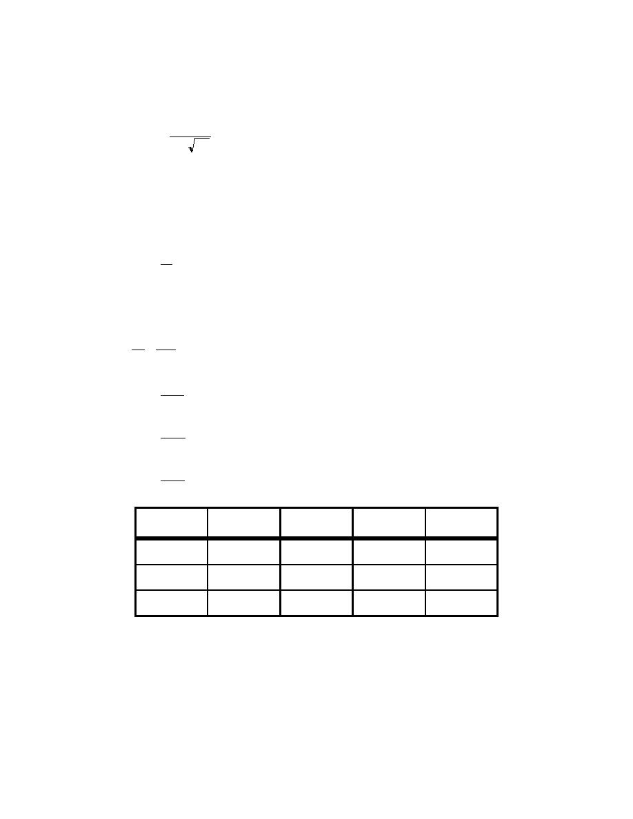
Calculations to determine the redundancy factor are tabularized below;
Story
Earthquake
rmax
Ax
rx
2
(ft )
Level
Direction
Third
Transverse
0.034
8,181
-4.5 < 1
Longitudinal
0.170
8,181
0.70 < 1.0
Second
Transverse
0.034
8,181
-4.50 < 1.0
Longitudinal
0.170
8,181
0.70 < 1.0
First
Transverse
0.034
8,181
-4.50 < 1.0
Longitudinal
0.170
8,181
0.70 < 1.0
Therefore, for all story levels; ρx,trans = 1.0, ρx,long = 1.0
B-9 Determine need for overstrength factor Ω o .
Per Paragraph 5.2.6.3.2 of FEMA 302, collector elements, splices, and their connections to resisting
elements shall be designed for the load combinations of Section 5.2.7.1 of FEMA 302. Therefore, for these
force controlled elements the following seismic load will be used;
For both the transverse or the longitudinal direction;
H2-26


 Previous Page
