CEMP-E
TI 809-02
1 September 1999
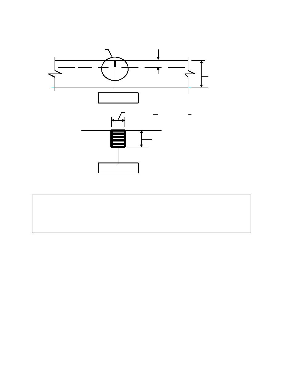
40 mm (1-1/2")
See Detail "A"
H
SECTION
W = 3 mm + 1.5mm (1/8" + 1/16")
H/4
DETAIL "A"
Figure 5-2. Control Joints.
Figure 5-2 Notes:
1. Concrete cover of 40 mm (1-1/2 inches) will be provided over reinforcement.
2. One-half of the welded wire mesh reinforcement (alternate wires) will be interrupted within 50 mm
(2 inches) of each side of slab control joints
(2) Isolation joints. Isolation joints form a separation of elements from the slab on
grade and permit both horizontal and vertical relative movement. Isolation joints should be
provided between the abutting faces of floor slab and fixed parts of the structure such as
columns, walls, and machinery bases. At locations where slabs abut vertical surfaces, such as
interior and exterior foundation walls and column pedestals, isolation joints will ordinarily be a
strip of 15-kg (30-pound) felt serving as a bond breaker. At exterior walls, perimeter insulation
extended to the top of slab will serve the purpose. Where slabs will expand due to radiant
heating systems, or extreme temperature changes, and where isolation from vibrations of
machinery and equipment foundations is required, joint filler 10 mm (3/8 inch) or more thick will
be required. Location and details of isolation joints will be shown on drawings. A typical
isolation joint is shown in Figure 5-3.
5-4


 Previous Page
