UFC 3-280-04
17 DEC 2003
the washer unit. In addition to providing transport, the eductor tube, or airlift system,
scours the media with air. The media undergo an additional cleaning step, usually in a
washbox located within the filter tank. A percentage of filtrate is allowed to flow upward
into the washbox, which is baffled, allowing for counter-current washing and gravity
separation of the cleaned sand and the concentrated waste solids. Solids generally are
discharged through a reject pipe for disposal. Alternatively, the media may be cleaned
in a separate washer unit. This type of system may not require compressed air. Instead,
water is used in the eductor pipe to transport sand to the media wash unit. The wash
process consists of a number of co-current media washes by filtered water within the
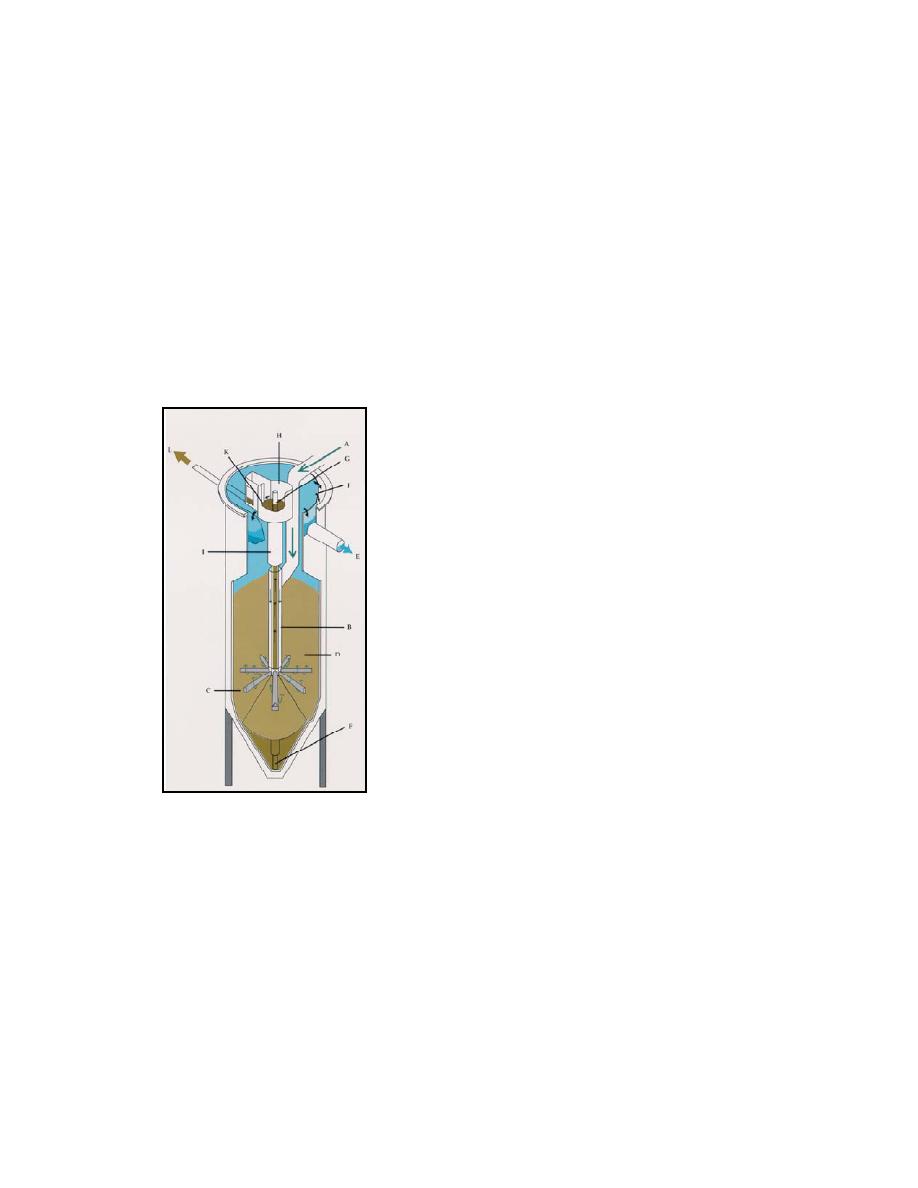
baffled media washer. Figure 5-7 shows a typical upflow continuous backwash system
configuration. (Andritz Sprout-Bauer, Inc., Eimco, Parkson Corporation.)
Figure 5-7. Typical Upflow Continuous Backwash System
A. Inlet
B. Feed Pipe
C. Feed Radials
D. Sand Bed
E. Filtrate Effluent
F. Airlift Pipe
G. Airlift Sand Effluent
H. Reject Compartment
I.
Sand
Washer/Separator
J.
Filtrate Weir
K. Reject Weir
Generally, the sand used in the upflow continuous backwash filter is coarser
than the sand layer in granular media filters used in batch processes (12 mm as op-
posed to 0.41 mm for the sand layer in dual media filters). The media depth will be on
the order of 1.2 m (4 ft) with a surface loading of 814 (m3/m2)/hr (3.35.7 gpm/ft2). The
backwash rate is typically about 10% of the surface loading. Because of the coarser
media grain size and the continuous agitation of the medium and removed solids, the
removal efficiency of the upflow continuous backwash filter is not as high as is available
through gravity and pressure granular media filters. Generally, effluent on the order of
10 mg/L TSS can be expected.
5-1.4.3 Downflow Continuous Backwash Filters. The downflow continuous back-
wash filter using granular media is also a proprietary system. Influent enters at the top
of the filter module (several modules are grouped together to create the filter cell, whose
size and shape will be determined by flow rate). The influent passes through layers of
5-24


 Previous Page
