UFC 3-280-04
17 DEC 2003
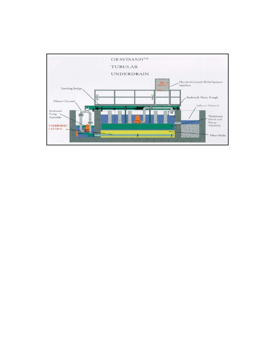
Figure 5-6. Traveling Bridge Filter (Section View)
5-1.4.1.2 Typically, traveling bridge filters operate at a normal dosing rate of 80
(L/min.)/m2 (2 gpm/ft2) or a peak loading of 200 (L/min.)/m2 (5 gpm/ft2). Their design
solids loading is typically on the order of 30 mg/L with a peak loading of 50 mg/L. Back-
wash rates are typically 800 to 1000 (L/min.)/m2 (20 to 25 gpm/ft2) of cell area for a pe-
riod of 1 to 2 minutes. Backwash usage will typically be 3% of design flow. Since filter
flow is by gravity, backwash water must be pumped to achieve sufficient head for bed
fluidization.
5-1.4.1.3 Traveling bridge filters offer the advantage of gravity filtration, plus the addi-
tional advantage of not periodically shutting down the system for backwash. In addition,
no backwash holding tanks are required, as backwash water is obtained from the efflu-
ent chamber and the filter can use a single medium. However, traveling bridge filters
may require excessive maintenance (electric gear motors, drive shafts, bearings to lube
and maintain), and they have also suffered alignment problems.
5-1.4.1.4 For more information, see Evolution of the Traveling Bridge Filter (Williams,
1995).
5-1.4.2 Upflow Continuous Backwash Filter. Granular media filters with upflow
continuous backwash are proprietary systems. The media are housed in a cylindrical
tank. Water enters the lower part of the filter tank and moves upward, contacting the
granular filtration media. Each manufacturer has its own influent dosing mechanism, by
which the influent stream is introduced to the filter bed. Generally, effluent is discharged
over an effluent weir. Concurrent to filtration, the media are constantly moving down-
ward, through the dirty sand hopper, to be removed from the filtration zone for washing,
and returned to the top of the filtration zone when clean. The media are removed from
the filter bed through an eductor pipe. The eductor pipe provides sufficient suction to the
media bed to draw the filter sand from the system. Compressed air is generally intro-
duced at the bottom of the pipe, causing the media to be drawn from the bed upward to
5-23


 Previous Page
