TM 5-822-14/AFJMAN 32-1019
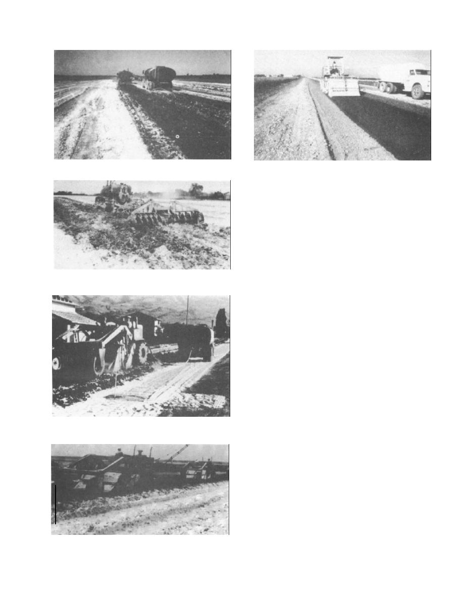
Figure 4-35. Watering of lime-treated clay on airport project.
Figure 4-39. Rotary mixer on primary road project.
side of the roadway. Lime is then spread on the
inside of each windrow or down the center line of
the road. The soil is then bladed to cover the lime.
After the lime is covered, the soil is mixed dry by
blading across the roadway. After dry mixing is
completed, water is added to slightly above the
optimum moisture content and additional mixing
is performed. To ensure thorough mixing by this
method, the material should be handled on the
mold board at least three times. When blade
mixing is used with the slurry method, the mixing
Figure 4-36. Mixing with a disc harrow.
is done in thin lifts that are bladed to windrows.
One practice is to start with the material in a
center windrow, then blade aside a thin layer after
the addition of each increment of slurry, thereby
forming side windrows. The windrowed material is
then bladed back across the roadway and com-
pacted, provided that its moisture content is at
optimum. A second practice is to start with a side
windrow, then blade in a thin 2-inch layer across
the roadway, add an increment of lime, and blade
this layer to a windrow on the opposite side of the
road. On one job this procedure was repeated
several times until all the material was mixed and
bladed to the new windrow. Because only one-half
of the lime had been added at this time, the
process was repeated, moving the material back to
Figure 4-37. Rotary mixer.
the other side. This procedure is admittedly slow,
but it provides excellent uniformity.
(d) Central mixing. Premixing lime with
granular base materials is becoming popular on
new construction projects, particularly where sub-
marginal gravels are used. Because the gravel has
to be processed anyway to meet gradation specifi-
cations, it is a relatively simple matter for the
contractor to install a lime bin, feeder, and pug-
mill at the screening plant. On one project a small
pugmill was installed at the head pulley of the
collecting belt conveyor (fig 4-20) and at another
operation a larger pugmill plant was utilized (fig
4-21). The general practice is to add the optimum
Figure 4-38. Train of rotary mixers.
4-18


 Previous Page
