UFC 3-240-13FN
25 May 2005
4-1.4.3
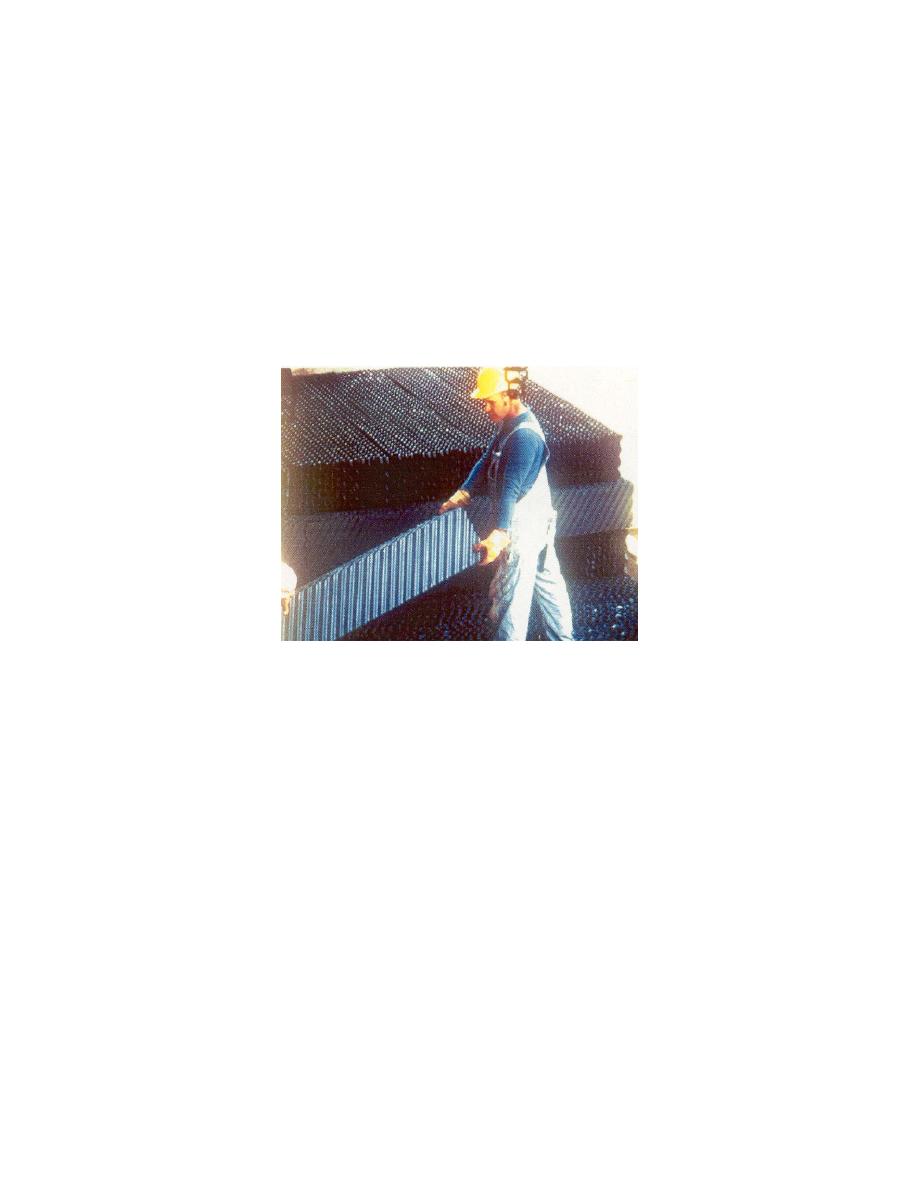
Fill. Fill is the internal part of a tower where air and water are mixed. The
fill intercepts the downward fall of water. The water is mixed with the air contained in the
fill material and water is evaporated and cooled. There are two types of fill: splash fill
and film fill. The falling water hits the splash fill, splashes, and breaks up into smaller
water droplets, resulting in an increased rate of evaporation. The splash fill is made of
wooden slats or bars, plastic, or ceramic tile. Film fill is a compact plastic material,
similar to a honeycomb, that causes water to flow over the fill material, creating a large
wet surface that maximizes evaporation as air travels past the film surface (see Figure
4-11).
Figure 4-11. High-Efficiency Cooling Tower Film Fill
4-1.4.4
Drift Eliminators. The drift eliminators efficiently remove water droplets
from the air and return the recovered water to the cooling tower, thereby minimizing the
loss of cooling tower water. They are located in areas that are situated after the fill and
water sprays and just before the area where the air exits the cooling tower (see Figures
4-6 and 4-8). Drift eliminators are also known as "mist eliminators."
4-1.4.5
Water Distribution and Fan Deck. In a cross-flow cooling tower, the hot
water basin is used to distribute the warm return water flow uniformly over the tower fill
(see Figure 4-6). In a counter-flow cooling tower, water sprays are used to distribute
the warm water (see Figure 4-8). The fan deck supports the motor and fan of the water
spray system. The stack is the structure (typically a cylinder) that encloses the fan and
directs warm, humid discharge air upward and out of the cooling tower.
4-1.4.6
Cell. This is the smallest subdivision of a large cooling tower in which the
fan can operate as an independent unit. A midwall casing must separate each end of
the cell from the adjacent cells to ensure all air flow induced by the cell fan is drawn only
through the cell fill and mist eliminator air path. Figure 4-7 illustrates a typical three-cell
cross-flow cooling tower. Figure 4-9 illustrates a typical four-cell counter-flow cooling
tower.
98


 Previous Page
