TM 5-814-5
litter. Indicate on the drawings the direction of
cm/sec.
(b) Provide an erosion layer of at least 6
prevailing winds, and where landfilling is to begin.
(4) Do not allow surface stormwater to enter
inches of earthen material capable of sustaining
trenches.
native plant growth.
(c) The designer can submit an alternative
(5) The floor of the landfill must have a 2 to 5
percent slope to drain leachate toward the collec-
design which must be approved by the appropriate
tion system. Follow the slope of the original grade
State or Federal agency.
to minimize excavation, and keep the depth uniform
(2) The actual design, however, will be depen-
to minimize leachate pumping.
dent on field conditions. A general design shown in
(6) Provide side slopes of 3 feet horizontal to 1
figure 3-5 consists of 12 inches or more of top soil,
foot vertical or flatter.
followed by a 12 inch drainage layer of sand, and a
(7) Provide a roadway constructed so that
hydraulic barrier of 24 inches of compacted clay
wastes can be placed at the bottom of the working
over a gas collection system. Drain tile or
face during inclement weather. The road surface
perforated pipe can be installed in the drainage
and slope are dependent on actual site conditions.
layer to facilitate drainage, however, they must be
A crushed stone surface and a maximum 6 percent
designed to prevent crushing. There must be 12 to
slope are recommended. The minimum width must
24 inches of compacted soil between the gas
be sufficient for two trucks to pass in opposite
collection system and the compacted waste. If a
directions unless anticipated traffic does not war--
sufficient quantity of good quality clay is not
rant it.
available, a 40 mil thick flexible membrane liner (20
(8) To minimize the amount of stormwater
mil minimum) is recommended. In some states both
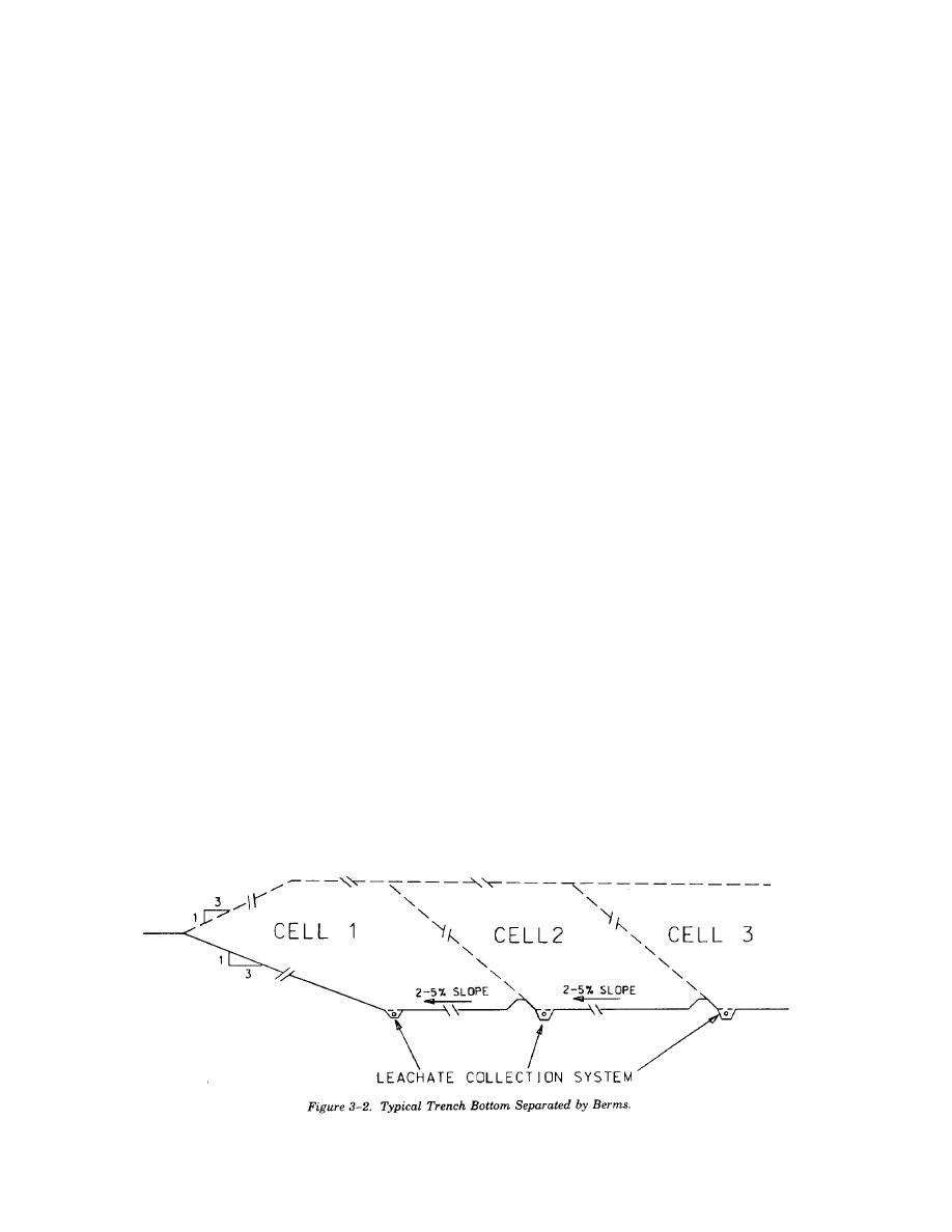
coming into contact with the waste, the trench can
a compacted clay layer and a flexible membrane
be constructed as a series of cells separated by
liner are required. Grass or other native vegetation
berms or by alternating the direction of the bottom
with finely branched root systems that will stabilize
slope as shown in figures 3-2 and 3-3. See figure 3-
the soil without penetrating the hydraulic barrier
4 for a typical berm detail.
must be planted. Trees must not be allowed to
(9) Provide for simple construction and opera-
grow in the cover unless necessary for the planned
tion methods.
final use of the landfill, and then must be enclosed
(10) For simple and economical operation, all
in planters. Generally, a much thicker soil layer is
wastes should be placed in a single trench unless
required for planted trees.
directions are given to segregate certain wastes.
(3) Generally, the drainage layer will consist of
c. Final Cover.
course sand, but if there is concern that burrowing
(1) 40 CFR 258 provides the following design
animals may penetrate the hydraulic barrier, the
criteria for final covers to minimize infiltration and
drainage layer should be comprised of aggregate.
erosion:
The size of the selected aggregate is dependent on
(a) Provide a hydraulic barrier of at least 18
the types of burrowing animals found in the area. In
inches of earthen material that has a permeability
most cases, size 357 per ASTM D 448 should be
less than or equal to that of the bottom liner system
specified. Size 357 is comprised predominantly of
or natural subsoil, but not greater than 1 x 10⁻⁵
2-inch stone with a small percentage as small as
3-3


 Previous Page
