TM 5-814-3/AFM 88-11, Volume III
(b) Countercurrent centrifuge. The centrifuge illustrated in figure 16-5 operates in the counter-
current mode. Influent sludge is added through the feed pipe; under centrifugal force, sludge solids settle
through the liquid to the bowl wall because their density is greater than that of the liquid. The solids are then
moved gradually by the rotating conveyor from left to right across the bowl, up the dewatering beach to
outlet ports and from there drop downward into a sludge cake discharge hopper. As the settled sludge solids
move from left to right through the bowl toward the sludge cake outlet, progressively finer solids are settled
centrifugally to the rotating bowl wall. The water or centrate drains from the solids on the dewatering beach
and back into the pool. Centrate is actually moved from the end of the feed pipe to the left, and is discharged
from the bowl through ports on the left end, which is the opposite end of the centrifuge from the dewatering
beach. The loca-tion of the centrate removal ports is adjustable and their location establishes the depth of the
pool in the bowl.
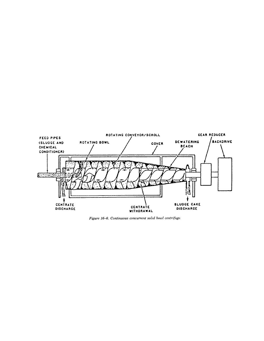
(c) Concurrent centrifuge. A second variation of the solid bowl centrifuge is the concurrent model
shown in figure 16-6. In this unit, liquid sludge is introduced at the far end of the bowl from the dewatering
beach, and sludge solids and liquid flow in the same direction. General construction is similar to the counter-
current design except that the centrate does not flow in a different direction than the sludge solids. Instead,
the centrate is withdrawn by a skimming device or return tube located near the junction of the bowl and the
beach. Clarified centrate then flows into channels inside the scroll hub and returns to the feed end of the
machine where it is discharged over adjustable weir plates through discharge ports built into the bowl head.
(d) Differential speed control. A relatively new development in solid-bowl decanter centrifuges is the
use of a backdrive to control the speed differential between the scroll and the bowl. The objective of the
backdrive is to control the differential to give the optimum solids residence time in the centrifuge and thereby
produce the optimum cake solids content. a backdrive of some type is considered essential when dewatering
secondary sludges because of the fine particles present. The backdrive function can be accomplished with a
hydraulic pump system, an eddy current brake, direct current variable speed motor or a Reeves-type variable
speed motor. The two most common backdrive systems are the hydraulic backdrive and the eddy current
brake.
(e) Installation. Most centrifuge installations have the centrifuge mounted a few feet above the floor
and use a belt conveyor to move dewatered cake away. Other methods of installing a solid bowl centrifuge
are to put the centrifuge on the second floor of a two-story building and drop the dewatered cake into either
trucks or a storage hopper on the first level; to mount the centrifuge about a foot off the floor and to drop
cake onto a screw conveyor built into the floor; or to let the centrifuge cake drop into an open-throated,
progressive cavity-type pump for transfer of the cake to a truck, incinerator or storage.
16-16


 Previous Page
