TM 5-814-3/AFM 88-11, Volume III
(2) Solid bowl centrifuge. Solid bowl centrifuge technology has greatly advanced in the past five to
six years, as both the conveyor life and machine performance have been improved. At many treatment plants
in the U.S., older solid bowl centrifuge installations have required very high maintenance expense due to rapid
wear of the conveyor and reduced performance. Recently the use of replaceable ceramic tile in low-G
centrifuges (<1, 100 Gs) and sintered tungsten carbide tile in high-G centrifuges (>1, 100 Gs) have greatly
increased the operating life prior to overhaul. In addition, several centrifuge manufacturers also offer stainless
steel construction in contrast to carbon-steel construction, and claim use of this material results in less wear
and vibration caused by corrosion. Revised bowl configurations and the use of new automatic backdrives and
eddy current brakes have resulted in improved reliability and process control, with a resultant improvement
in dewatering performance. Also in recent years, several centrifuge manufacturers have reduced the
recommended throughput of their machines in direct response to competition from the belt filter press. This
has allowed for an increase in solids residence time in the centrifuge and subsequent improvement in cake
dryness.
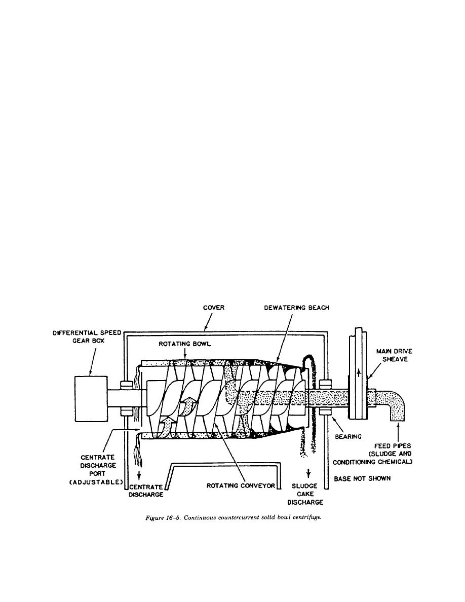
(a) Physical description. As opposed to the semi-continuous feed/discharge cycles of the imperforate
basket centrifuge, the solid bowl centrifuge (also called decanter or scroll centrifuge) is a continuously
operating unit. This centrifuge, shown in figure 16-5, consists of a rotating, horizontal, cylindrical bowl
containing a screw-type conveyor or scroll which rotates also, but at a slightly lower or higher speed than
the bowl. The differential speed is the difference in revolutions per minute (rpm) between the bowl and the
conveyor. The conveying of solids requires that the screw conveyor rotate at a different speed than the bowl.
The rotating bowl, or shell, is supported between two sets of bearings; and at one end, necks down to a
conical section that acts as a dewatering beach or drainage deck for the screw-type conveyor. Sludge enters
the rotating bowl through a stationary feed pipe extending into the hollow shaft of the rotating conveyor and
is distributed through ports in this hollow shaft into a pool within the rotating bowl.
16-15


 Previous Page
