TM 5-814-3/AFM 88-11, Volume III
12-4. Secondary sedimentation tanks.
The purpose of secondary sedimentation tanks is to allow the biological solids in the wastewater leaving the
trickling filter to settle out. This produces an effluent for discharge, and the settled solids can be recirculated
to the trickling filter to enhance its performance. Chapter 11 provides additional details on the design of
secondary sedimentation systems.
a. Design philosophy. The tanks will be designed for either the average daily flow rate or the daily flow
equivalent to the peak 3-hour flow rate, whichever is greater. All of the appurtenant piping, channels, inlets,
outlets and weirs will be designed to handle the peak flow rate. If there are no data for peak flow rates
available, then a value of 3 times the average flow rate will be used. Two tanks, operating in parallel, will be
used in all treatment plants with a design capacity greater than 0.1 million gallons per day. Each tank will be
designed to treat 67 percent of the design flow. A single tank may be used in treatment plants with design
capacity less than 0.1 million gallons per day but an equalization tank or holding basin must be provided to
provide some settling capacity for those times when the secondary sedimentation requires maintenance.
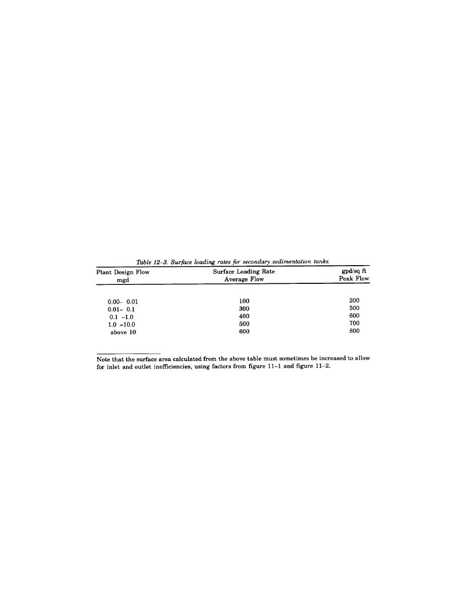
b. Design criteria. The sedimentation tanks should be designed for either the average flow rate or peak
flow rate, whichever requires the largest surface area. The following table presents the design criteria for
various size treatment plants:
12-5. Other filter components.
Table 12-4 gives a list of other components normally associated with trickling filters and for which design
requirements are specified. Trickling filter design must include provisions for flooding the filter and the filter
walls, and appurtenances must be able to structurally withstand the resulting hydrostatic pressure forces when
the filter is flooded. In northern regions that are subject to extreme and/or prolonged freezing conditions,
including high wind chill factors, design considerations must be given to providing filter dome covers or
windbreaks. Figure 12-2 is a sectional view of a trickling filter.
12-8


 Previous Page
