TM 5-820-3/AFM 88-5, Chap. 3
c. Adequate freeboard is most important in the
design of a concrete chute. The critical section
where most failures have occurred is at the en-
trance where the structure passes through the berm.
As indicated earlier, a minimum freeboard equal to
one and one-half times the computed depth of flow
is recommended. A minimum depth of 3 inches is
suggested for the chute. Minor irregularities in the
finish of the chute frequently result in major flow
disturbances and may even cause overtopping of
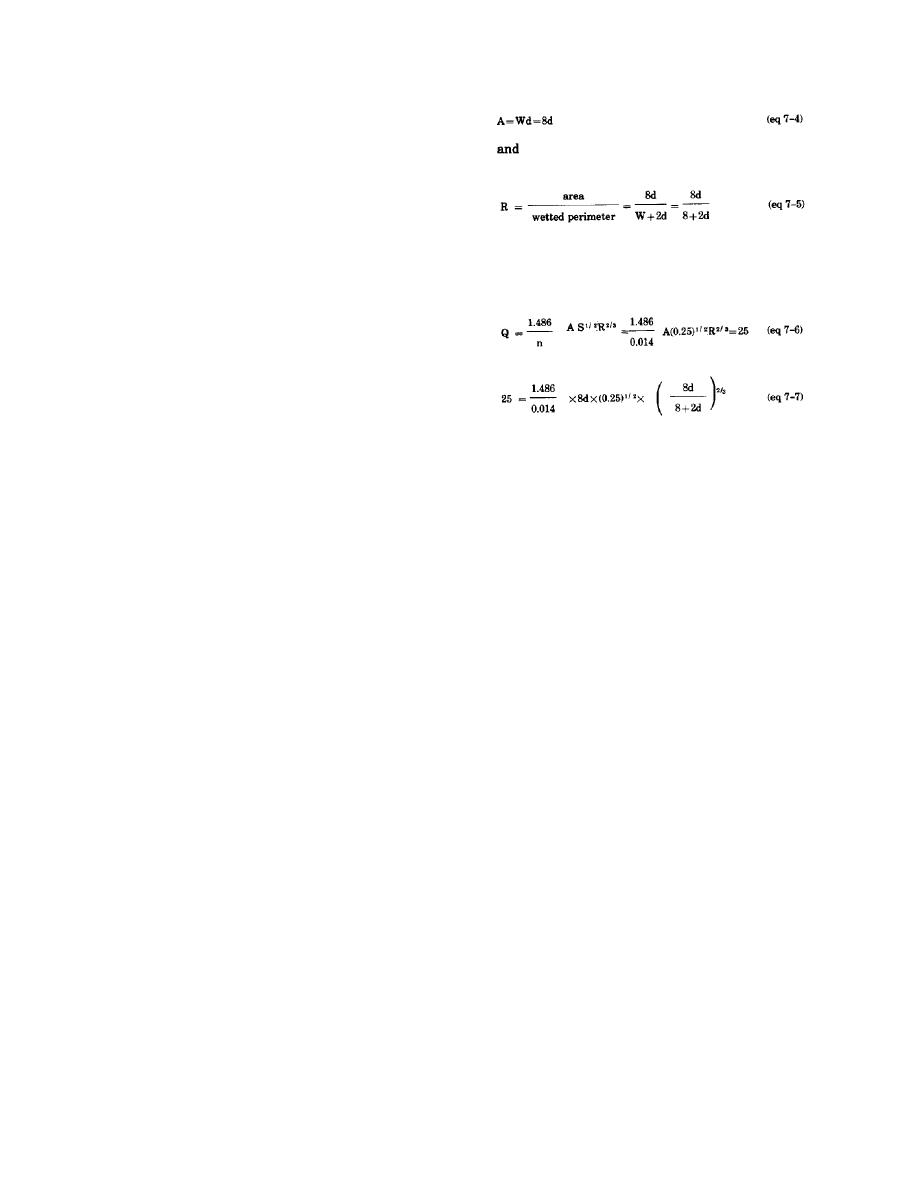
Use Manning's equation (7-2) to determine depth
sidewalls and structural failure. Consequently,
of water:
special care must be given to securing a uniform
concrete finish and adequate structural design to
minimize cracking, settlement, heaving, or
creeping. A suitable means for energy dissipation or
erosion prevention must be provided at the end of
the chute.
7-3. Design problem.
a. Design a concrete chute to carry 25 cubic feet
Solving for d by trial and error, the depth of water
per second down a slope with a 25 percent grade.
is d=0.186 foot. For use in figure 7-4, the size of
The allowable head is 1 foot and Manning's n is
the angle of the chute is equal to 0.243 and q=Q/
0.014.
W=25/8=3.125. Thus, S/q1/5 equals 0.1935, which
b. Solution one. Using equation 7-1 with no
corresponds to a design air concentration T = dair/
drop at the entrance, Q=3.1W(H)1/5, with Q=25
(dair+d)=0.471. Solving for dair gives 0.166 foot.
cubic feet per second and H = 1 foot.
Then, the total depth of flow is depth of water plus
depth of air, 0.352 foot. Wall height should be 1.5
25=3.1W(1)1/5 or W=8.06 feet
(eq 7-3)
times the total depth of flow or 0.528 foot. One
should use 0.5 foot. This design is shown in figure
Use W = 8 feet
7-5.
Now
7-6


 Previous Page
