Maximum concrete aggregate size should be one third
faces of shaft foundations when wetting of surround-
of the openings in the reinforcement cage.
ing expansive soil occurs. Side friction resulting in up-
lift forces should be assumed to act along the entire
d. Grade beams. Grade beams spanning between
depth of the active zone since wetting of swelling soil
shafts are designed to support wall loads imposed ver-
causes volumetric expansion and increased pressure
tically downward. These grade beams should be iso-
against the shaft. As the shaft tends to be pulled up-
lated from the underlying swelling soil with a void
ward, tensile stresses and possible fracture of concrete
space beneath the beams of 6 to 12 inches or 2 times
in the shaft are induced, as well as possible upward dis-
the predicted total heave of soil located above the base
placement of the entire shaft.
of the shaft foundation (whichever is larger). Steel is
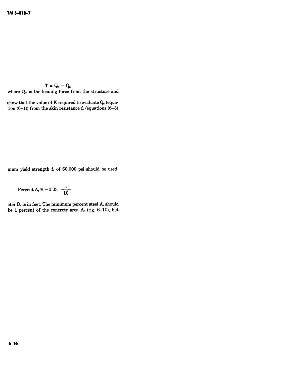
(a) The tension force T (a negative quantity)
recommended in only the bottom of the grade beam if
may be estimated by
grade beams are supported by drilled shafts above the
(6-6)
void space. Grade beams resting on the soil without
void spaces are subject to distortion from uplift pres-
includes the weight of the shaft. Limited observations
sure of swelling foundation soil and are not recom-
mended.
(1) Preparation of void space. Construction of
and (6-4)) varies between 1 and 2 in cohesive soils for
grade beams with void spaces beneath the beams may
shafts subject to uplift forces. The same swelling re-
require overexcavation of soil in the bottom of the
sponsible for uplift also increases the lateral earth
grade beam trench between shafts. The void space may
pressure on the shaft. Larger K values increase the
be constructed by use of sand that must later be blown
computed tension force.
away at least 7 days after concrete placement, or by
(b) The shaft should be of proper diameter,
use of commercially available cardboard or other re-
length, and underreaming, adequately loaded, and
tainer forms that will support the concrete. The card-
contain sufficient reinforcing steel to avoid both ten-
board forms should deteriorate and collapse before
sile fractures and upward displacement of the shaft.
swell pressures in underlying soil can deflect or dam-
ASTM A 615 Grade 60 reinforcing steel with a mini-
age the grade beams. The resulting voids should be
protected by soil retainer planks and spacer blocks.
The minimum percent steel required if ASTM A 615
Figure 6-12 illustrates some void details.
Grade 60 steel is used is given approximately by
(2) Loading. Interior and exterior walls and con-
T
centrated loads should be mounted on grade beams.
(6-7)
Floors may be suspended from grade beams at least 6
inches above the ground surface, or they maybe placed
where T is the tension force in tons and the shaft diam-
directly on the ground if the floor slab is isolated from
the walls. Support of grade beams, walls, and suspend-
ed floors from supports other than the shaft founda-
more may be required. The reinforcing steel should be
tion should be avoided. Figure 6-13 illustrates typical
hooked into any existing bell as shown in figure 6-10,
exterior and interior grade beams.
and it may also be hooked into a concrete grade beam.


 Previous Page
