TM 5-818-1 / AFM 88-3, Chap. 7
(Courtesy of F. E. Richart, Jr., J. R. Hall, Jr., and R. D. Woods.
Vibrations of Soils and Foundations, 1970, p 91. Reprinted by
permission of Prentice-Hall, Inc., Englewood Cliffs, N. J.)
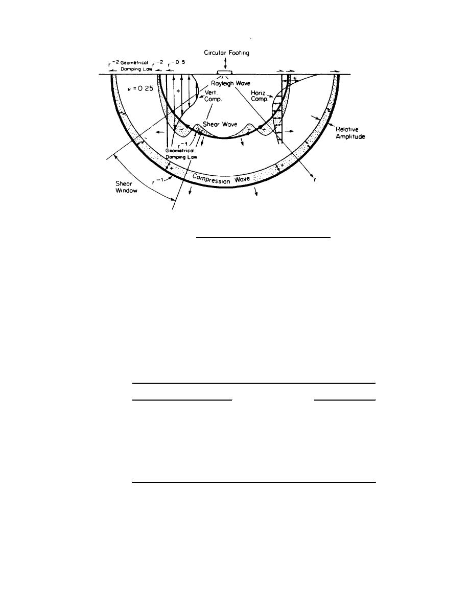
Figure 17-7. Distribution of displacement waves from a circular footing on the elastic half-space.
soil-foundation system is the shear modulus, G. The
wave velocity through soil or from special cyclic
shear modulus can be determined in the laboratory or
laboratory tests.
b. Field wave velocity tests. S-wave velocity
estimated by empirical equations. The value of G can
also be computed by the field-measured S-wave velocity
tests are preferably made in the field. Measurements
and equation (17-16).
are obtained by inducing a low-level seismic excitation at
a. Modulus at low strain levels. The shear
one location and measuring directly the time required for
modulus and damping for machine vibration problems
the induced S-wave to travel between the excitation and
correspond to low shear-strain amplitudes of the order of
pickup unit. Common tests, such as uphole, downhole,
-4
1 to 3 x 10 percent. These properties may be
or crosshole propagation, are described in geotechnical
determined from field measurements of the seismic
engineering
literature.
Table 17-3. Attenuation Coefficients for Earth Materials
a
Materials
a (1/ft) @ 50 HZ
Sand
Loose, fine
0.06
Dense, fine
0.02
Clay
Silty (loess)
0.06
Dense, dry
0.003
Rock
Weathered volcanic
0.02
Competent marble
0.00004
U. S. Army Corps of Engineers
17-10


 Previous Page
