TM 5-805-4
c. For oil-and resin-based caulking, the depth
should be one to three times the width, and the
joint should be subject to very little movement.
d. For elastomeric sealants, when the joint is
wider than 13 mm ( inch), the depth should be
the width but never less than 13 mm ( inch). For
widths in excess of 50 mm (2 inches), the depth
should be as specified in the sealant manufactu-
rer's recommendations.
7. Calculation of Joint Size. Sizes of most butt
joints can be determined using one of the proce-
dures in ASTM C 1193; one of these procedures
makes use of a nomogram to approximate joint
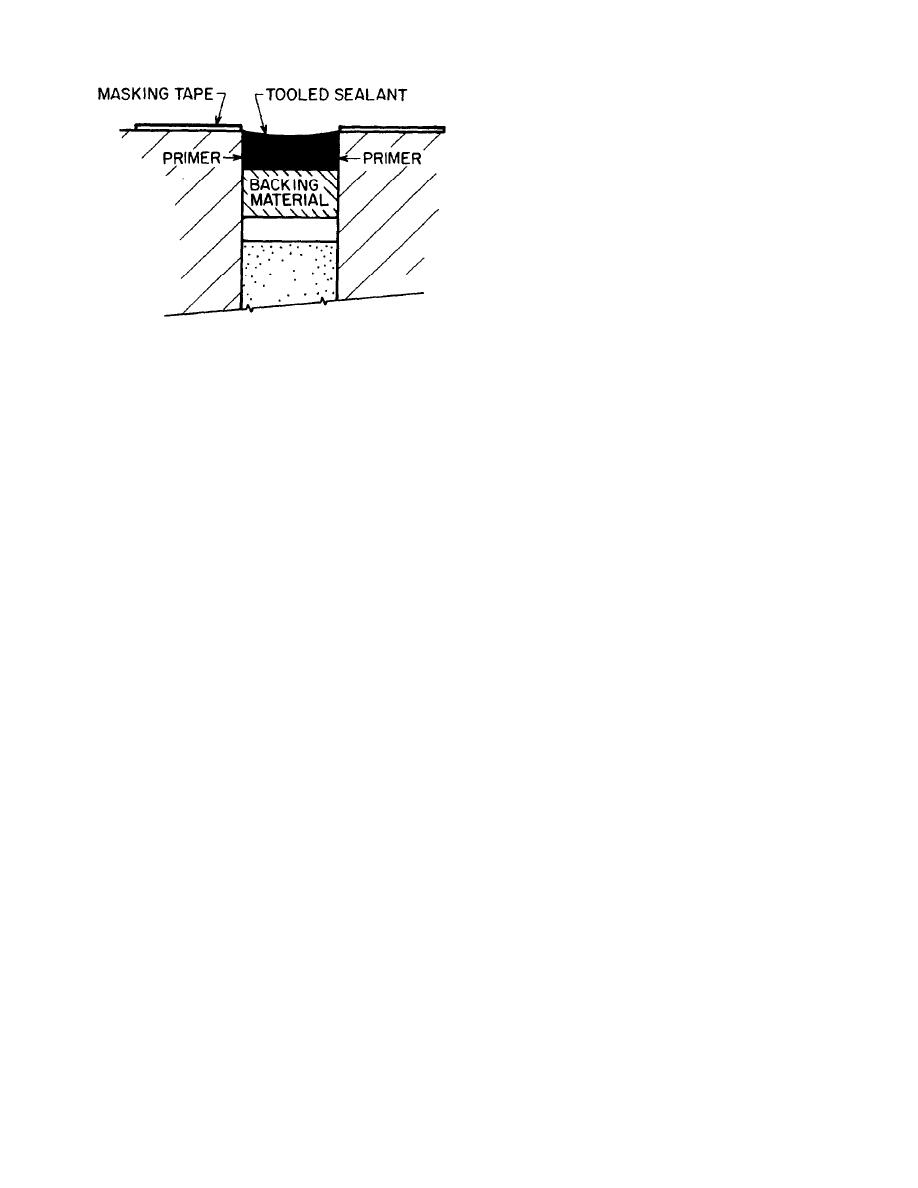
Figure 5. Backing Material in a Deep Joint.
width requirements for various combinations of
substrate materials and sealants; a method is also
used in the project. Where temperature ranges are
provided for calculating the joint-width (compres-
moderate, as for most building interiors (and some
sion) based on expansion of adjacent materials.
sheltered exteriors), thermal movement will be
Similar calculations are described below for both
limited. In general, plastics and metals have more
compression and for extension of joints. Calcula-
thermal movement than stone, glass, masonry,
tions are more complicated for configurations such
and concrete.
as overlaps, fillets, or corners; these joints should
(1) In cold regions, the joint expands as the
be designed as recommended by the sealant or
temperature falls and the substrate materials con-
substrate manufacturer.
tract. More often in the rest of the world, the joint
a. Substrate service temperature. Joint size
is compressed as the temperature rises.
should be based on the largest change in tempera-
(2) The service temperature of the substrate
ture expected for the service life of the joint and
material is not limited by the ambient tempera-
its adjacent materials.
ture but may be increased by solar absorption or
b. Compression. When materials next to a joint
decreased by radiation to a clear cold night sky.
are heated, they expand and compress the sealant
Thus, service temperature is the extreme highest
in the joint. This compression is often the most
or lowest temperature experienced by the material
severe distortion that the sealant must tolerate.
during its service life. For most joints, this ex-
The temperature range for the maximum expan-
treme temperature change causes the maximum
sion of the materials is the difference between the
joint movement.
highest service temperature and the lowest sealant
(3) A range of application temperatures is
application temperature.
specified by the manufacturer for each sealant,
(1) In direct solar radiation, the highest ser-
vice temperature will exceed the ambient tempera-
and either the low or high end of this range is
ture, roughly in proportion to the solar absorption
selected as needed to produce the greatest temper-
coefficient of the surface, unless limited by the
ature range, i.e., the greatest difference, or
material's heat capacity. For example, a black
change, between application and extreme service
surface may absorb as much as 95 percent of the
temperature. This temperature change is used for
solar radiation, and an exterior insulation and
calculating the joint width.
finish system or insulated metal panel will have
6. Approximate Joint Dimensions. The follow-
low heat capacity, i.e., the heat cannot be readily
ing guidelines provide approximate joint dimen-
absorbed or dissipated. Reflected solar radiation
from adjacent surfaces may also have to be consid-
sions for use when anticipated temperature ranges
ered.
and joint movement are limited. A detailed design
(2) The maximum substrate material tempera-
procedure is recommended when temperature
ture T(max) is determined by adding the hottest
ranges are large or where other factors contribute
ambient summer temperature Ta(max) to the radi-
to joint movement.
ative heat gain XC using equation 1:
a. For side-bonding field-formed sealants, a rela-
T(max) = Ta(max) + XC
(eq. 1)
tively shallow joint is better and usually more
Where X = 100 for low heat capacity substrate material
economical than a deep joint.
X = 75 for high heat capacity substrate material
b. The minimum joint width should always be 6
C = Coefficient of solar absorption for the substrate
mm ( inch).
material.
3


 Previous Page
