TM 5-809-6/AFM 88-3, Chap. 6
Handbook by Gaylord & Gaylord for circular steel stacks.
conveying a gas of different specific gravity than atmospheric
Components will be proportioned so that resonance due to
conditions and to temperature differential stresses caused by
vortex shedding at low wind velocities is avoided. For duct
an uneven temperature distribution within the stack. See also
of rectangular cross section, structural design will be in
ASCE Design and Construction of Steel Chimney Liners.
(1) Reinforced concrete stacks. Reinforced concrete
accordance with the AISI Design of Plate Structures, Design
of Welded Structures by Blodgett, and applicable portions of
stacks will be designed in accordance with ACI 307.
(2) Aluminum stacks. If constructed of aluminum,
the American Institute of Steel Construction (AISC)
Specification for Structural Steel Buildings Allowable Stress
design of stacks will follow similar design guidance and
Design and Plastic Design that relates to plate girders.
general references given for design of steel stacks.
(3) Steel stacks.
Design will include a determination of plate thickness
(a) Design of steel stacks will be in accordance with
required to resist flexural loading, the size and spacing of
stiffeners, the size and location of internal bracing, and
the AISC Specification for Structural Steel Buildings
additional plate thickness and features which may be
Allowable Stress Design and Plastic Design; Structural
required if the duct is designed as a spanning box girder.
Engineering Handbook by Gaylord & Gaylord; SMACNA
b. Stacks. In addition to maximum loadings, stacks will
Guide for Steel Stack Design and Construction; and ASME
be designed to resist the effects of vortex shedding or
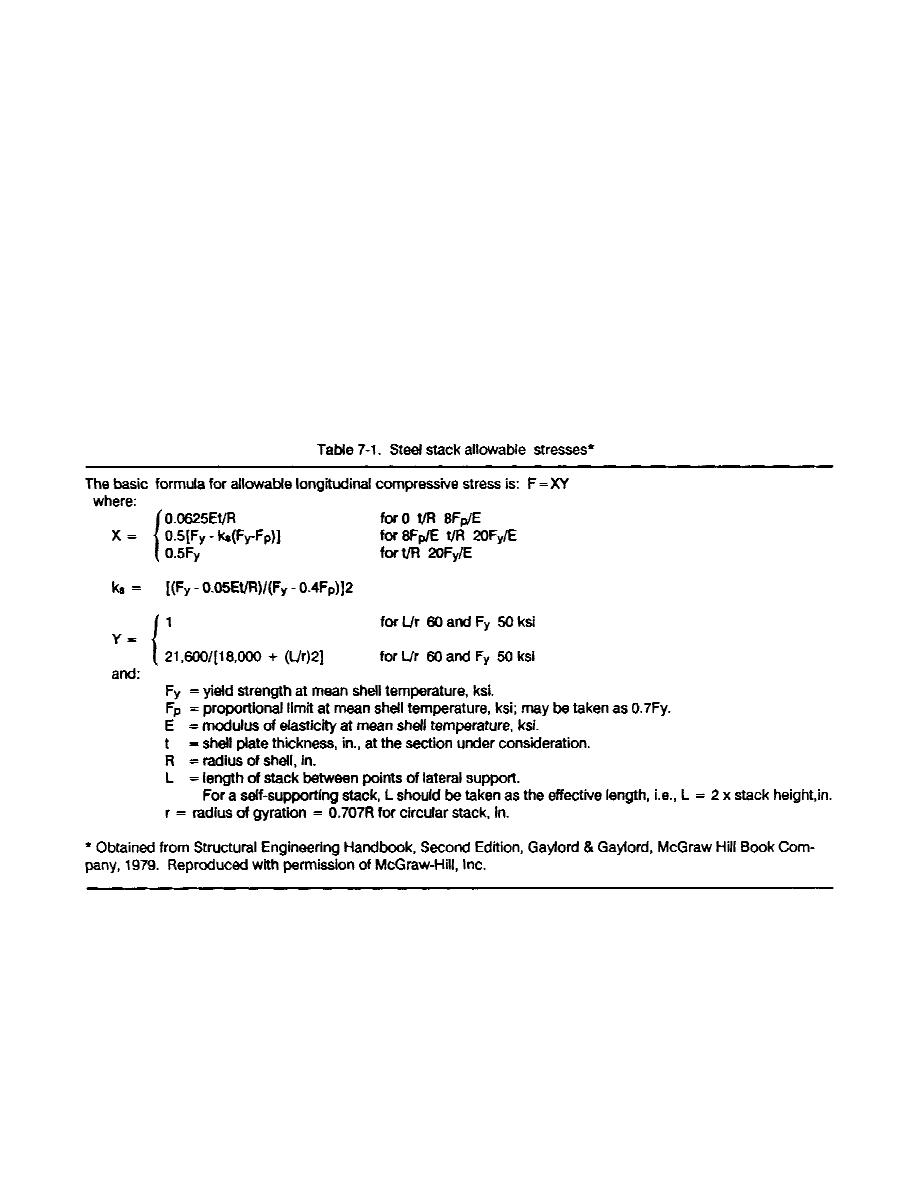
STS-1. Allowable stresses will be in accordance with table
fluttering caused by steady wind. Stack designs will consider
7-1. The allowable stress is for a design condition of dead
pressure differential stresses caused by virtue of the stack*s
load combined with either seismic or wind loads.
(b) Shell thickness will be at least 1/4 inch for lined
bolt hole areas) will be used to determine actual stresses.
stacks and 5/16 inch for unlined stacks. The computed shell
Allowable stresses for parts other than the shell plate will be
thickness will be increased by 1/16th inch to allow for
in accordance with AISC Specification for Structural Steel
possible corrosion. The net section area (gross area minus
Buildings Allowable Stress Design and Plastic Design.
7-2


 Previous Page
