CEMP-E
TI 809-07
30 November 1998
sections with a thickness equal to the maximum permitted based on the column-to-anchor weld thickness
(see Table 3-4).
The limitation on angle thickness will cause the angle to yield in bending at the angle corner, so that it
provides little resistance to uplift by itself. Uplift resistance shall be increased by adding a plate over the
horizontal leg of the angle.
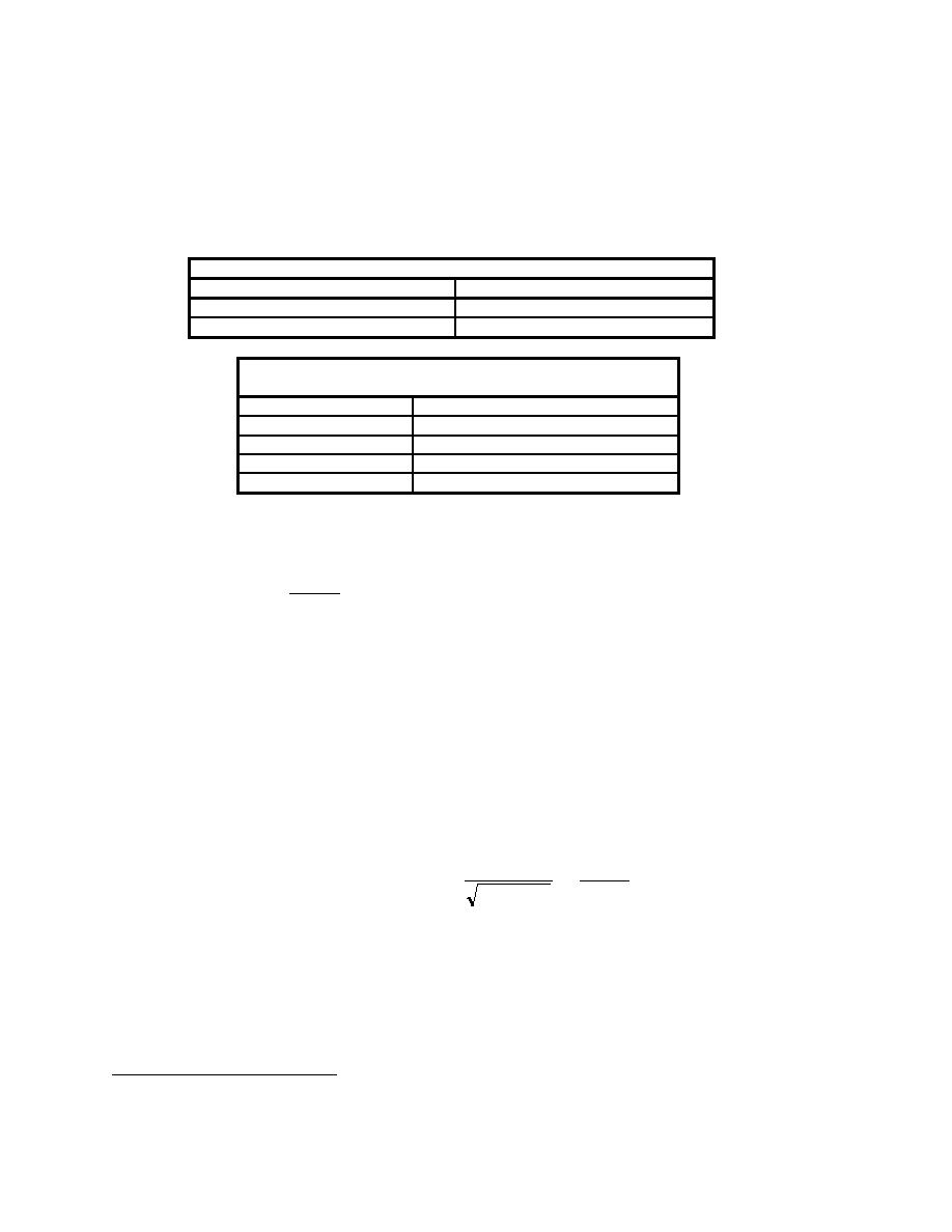
Table 3-3. Maximum Column-to-Anchor Weld Thickness.7
Column Material Thickness, tc
Maximum Weld Thickness, tw
tc < 6 mm ( inch)
Tw = tc
tc ≥ 6 mm ( inch)
tw = tc 1.5 mm (tc 1/16 inch)
Table 3-4. Maximum Angle Thickness Based on Column-
to-Anchor Weld Thickness.8
Weld Thickness, tw
Maximum Angle Thickness, tA
3 mm (1/8 inch)
6 mm (1/4 inch)
5 mm (3/16 inch)
13 mm (1/2 inch)
6 mm (1/4 inch)
19 mm (3/4 inch)
9
8 mm (5/16 inch)
29 mm (1-1/8 inch)
The column-to-angle weld design strength, PA shall exceed the total uplift force applied to one angle at
one side of the column due to uplift and bending. This is expressed as follows:
Pvy max
+ PM ≤ PA = PT + PG
(Eq 3-25)
2
Where:
PA = the total vertical design capacity of the column-to-angle weld
PT = the design strength of the transverse loaded fillet weld at the horizontal column-to-angle
weld (Equation C-56)
PG = the design strength of the longitudinal loaded flare bevel grove weld at the vertical column-
to-angle welds at the corner of the columns. The design strength for this column-to-angle
weld shall be determined based on AISI guidance (Section E2.5 Flare Grove Welds). The
application of this guidance to the design of column-to-angle welds is summarized in
Appendix C (Paragraph C17).
Pvymax = the net anchor vertical load at the maximum yield stress in the diagonal straps,
expressed by:
GL min
H
= Fsy max n sb s t s
-
Pvy max
(Eq 3-26)
H +W
2
2
2
Where:
GLmin = the minimum gravity load per shear panel, i.e., (0.9 - 0.2SDS)D in Equation C-18.
PM = the uplift force capacity per anchor angle, beyond Pvymax/2 available to resist moment is
determined by Equation 3-27. This assumes the anchor bolts are sufficiently tightened to
provide a moment restraint.
7
nd
AISC Load and Resistance Factor Design (LRFD) Specification, 2 Edition, 1994, Section J2b.
8
AISC LRFD, Table J2.4
9
Maximum thickness of standard angles.
3-13


 Previous Page
