TM 5-809-3/NAVFAC DM-2.9/AFM 88-3, Chap. 3
8-6. Lateral support. When the tops of lintels are at the tops of walls or when the provisions of this chapter
are used to design concrete masonry beams other than lintels, the compression face of the lintel or beam must
be given lateral support. The clear distance between points of lateral support of the compression face will not
exceed 32 times the least width of the compression face.
8-7. Design aids. Appendix C provides design tables to aid the designer in designing masonry lintels.
8-8. Design examples.
a. Design example 1.
(1) Given.
(a) 8-inch CMU nonloadbearing wall
(b) Wall height = 12 feet
(c) f`m = 1350 psi
(d) Fm = 1/3f*m = 450 psi
(e) Em - 1000f'm - 1,350,000 psi
(f) Type S mortar
(g) Reinforcement
fy = 60,000 psi
Fs = 24,000 psi
Es = 29,000,000 psi
(h)
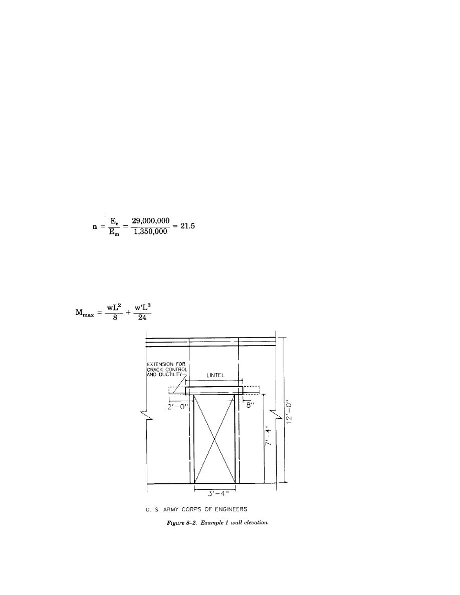
(i) A door opening 3*-4" wide by 7*-4" high is located in the wall as shown in figure 8-2.
(2) Problem. Design the lintel over the door.
(3) Solution. Due to the location of the lintel within the wall panel, the confining end thrust necessary
to provide arching action may be assumed. Therefore, the lintel must support its own weight plus the weight
of the triangle of masonry above the door and below the arch. Assume an 8-inch by 8-inch CMU lintel.
Flexural Check
(a) Determine the maximum moment due to the loading, Mmax, as follows:
8-3


 Previous Page
