TM 5-809-3/NAVFAC DM-2.9/AFM 88-3, Chap. 3
Where:
fr = The modulus of rupture, which is provided in chapter 5.
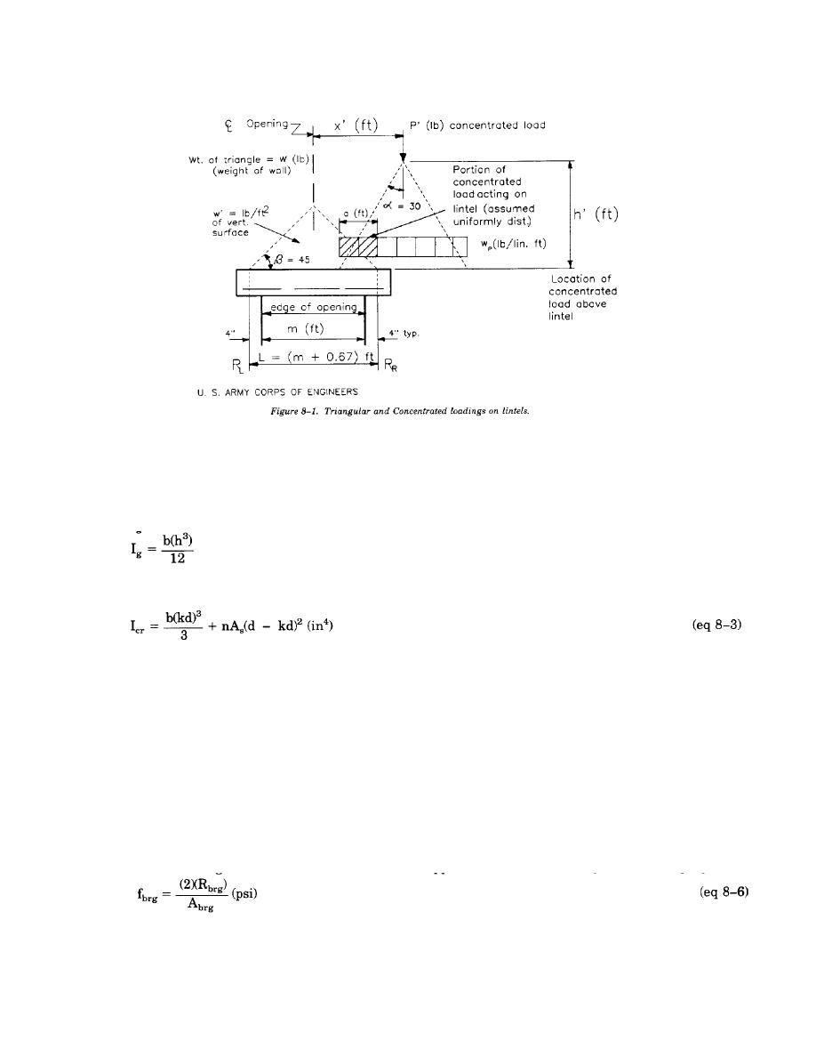
Yt = The distance from the compression face to the neutral axis of the lintel, inches.
Ig = The moment of inertia of the uncracked lintel cross section about the centroid, in4.
b = The actual width of the lintel, inches.
h = The total depth of the lintel, in.
Icr = The moment of inertia of the cracked section of the lintel, in4.
Values of Icr for most masonry lintels are provided in the tables in appendix B. For continuous members, the
effective moment of inertia may be taken as the average of values obtained from equation 8-1 for the critical
positive and negative moment sections. Ie will not be assumed greater the Ig.
b. Total deflection (long term). For masonry lintels, the total deflection, )mt, will be the deflection due
to short term loadings, )ms, (such as live loading and transient dead loadings) combined with the deflections
due to long term dead loadings, )ml, as follows:
)mt = )ms + (3)()ml) (inches)
(eq 8-4)
8-5. Bearings pressure at lintel reaction. The minimum bearing length will be eight inches. The minimum
bearing area, Abrg, will be:
Abrg = 8b (in2)
(eq 8-5)
Fully grouted cores are required below the lintel bearing area. It is reasonable to assume a triangular stress
distribution when determining the maximum bearing stress, fbrg. When this assumption is made, the maximum
bearing stress occurs at the face of the support and is determined by the following equation:
Where:
Rbrg = The end reaction of the lintel, lbs.
The maximum bearing stress will not exceed the allowable bearing stress, which is given in chapter 5. If the
lintel is restrained against rotation at the support, a uniform stress distribution will be assumed.
8-2


 Previous Page
