By inspection of this diagram, it is clear that a plastic hinge will form on the right side of the beam where
the moments are greatest (with increased loading, the moments will increase proportionately until yielding
occurs).
The stress ratio on the right side is;
187.65ft - kips (12"/1' ) / 123 - in3
M toe / Sx,toe
σ toe- of - haunch
=
=
= 1.96 > 1.2
O.K.
σ face- of - column M face / S x,haunch 208.16ft - kips (12"/1' ) / 268 - in3
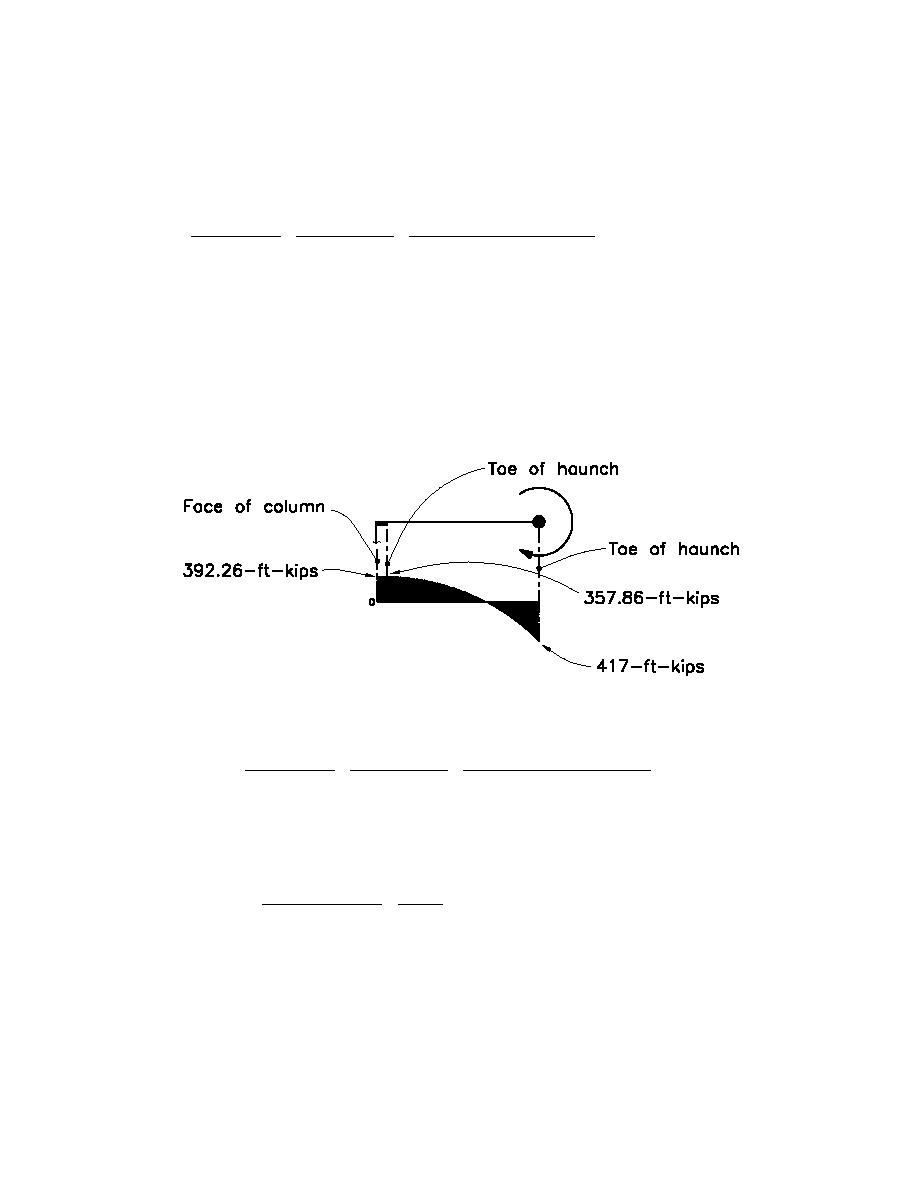
The left side was investigated by placing a plastic hinge at the assumed hinge location on the right side and
analyzing the resulting configuration. The lateral load was increased until yielding occurred at the toe of
the haunch on the left side.
M p = Z x Fy = 139 - in3 (36ksi) = 417 ft - kips (565.5KN-m)
M y = S x Fy = 123 - in3 (36ksi) = 369 ft - kips (500.4KN-m)
The resulting moment diagram, showing moments at the face of column and at the toe of the haunch, is as
follows;
1-ft-kip = 1.356KN-m
The resulting stress ratio on the left side is;
357.86ft - kips (12"/1' ) / 123 - in3
M toe / S x,toe
σ toe- of - haunch
=
=
= 1.99 > 1.2
O.K.
σ face- of - column M face / S x,haunch 392.26ft - kips (12"/1' ) / 268 - in3
Check unbraced length of the compression flanges (per AISC seismic requirements);
Try 5'on center (same spacing as the perpendicular floor joists);
2500(2.48" )(1'/12" ) 2500ry
L b = 5' < 14.4' =
=
O.K.
(1.53m < 4.39m)
36ksi
Fy
Note: By inspection, the high roof moment frame with a truss will be acceptable.
Braces:
Try TS 4.5x4.5x1/4 (TS 114.3mmX114.3mmX6.4mm)
Check DCR in compression;
QCE = 1.25Pn = 1.25(34.1k) = 42.6k (189.5KN)
H4-49


 Previous Page
