UFC 3-260-02
30 June 2001
proposed for a specific project is provided in EI 02C202/AFJMAN 32-1016 and TM 5-818-8/
AFJMAN 32-1030.
(3) Bound base also has significant structural value and is considered to be a low-strength
concrete for design purposes. A minimum 200-millimeter (8-inch) drainage plus separation layers
must be placed between the bound base and the subgrade.
(4) If sufficient high-quality base material is not locally available, the nonfrost design base
layer thickness can be used. The appropriate FAIR value will be used for the base to determine the
PCC thickness.
(5) The subgrade preparation techniques and transition details outlined in this chapter are
also required for the design of overrun pavements.
(6) The control of differential frost heave at small structures is located within shoulder
pavements. To prevent objectionable heave of small structures inserted in shoulder pavements,
such as drain inlets and bases for airfield lights, the shoulder base and subbase courses extending
at least 1.5 meters (5 feet) radially from the structures should be designed and constructed entirely
with nonfrost susceptible material to a depth to prevent subgrade freezing. Gradual transitions are
required. Alternatively, synthetic insulation could be placed below a base to prevent the advance
of freezing temperatures into the subgrade; suitable transitions to the adjoining uninsulated
pavement would be needed.
6. LIMITED SUBGRADE FROST PENETRATION METHOD. This design method permits a small
amount of frost penetration into frost susceptible subgrades. The procedure uses a design freezing
index (DFI) as illustrated in Figure 20-2. Typical DFI values are shown in Figures 20-3 and 20-4.
The procedure is described in the following subparagraphs. A computer program (PDSF) for
providing the limited subgrade frost penetration design thickness is discussed in Chapter 1.
a. Step One. Determine frost penetration depths. The maximum frost penetration depths with
respect to the design freezing index shown in Figure 20-5 are calculated from the Modified
Berggren formula and computational procedures outlined in TM 5-852-6/AFM 88-19, Chap. 6.
Frost penetration depths presented in Figure 20-5 are measured from the pavement surface. The
pavement is considered free of snow and ice. Computations also assume that all soil beneath the
pavement within the depth of frost penetration are granular and nonfrost susceptible. It was
assumed in the computations that all soil moisture freezes at 0 degrees Celsius (32 degrees
Fahrenheit). Use straight-line interpolation where necessary. The frost penetration depth a in
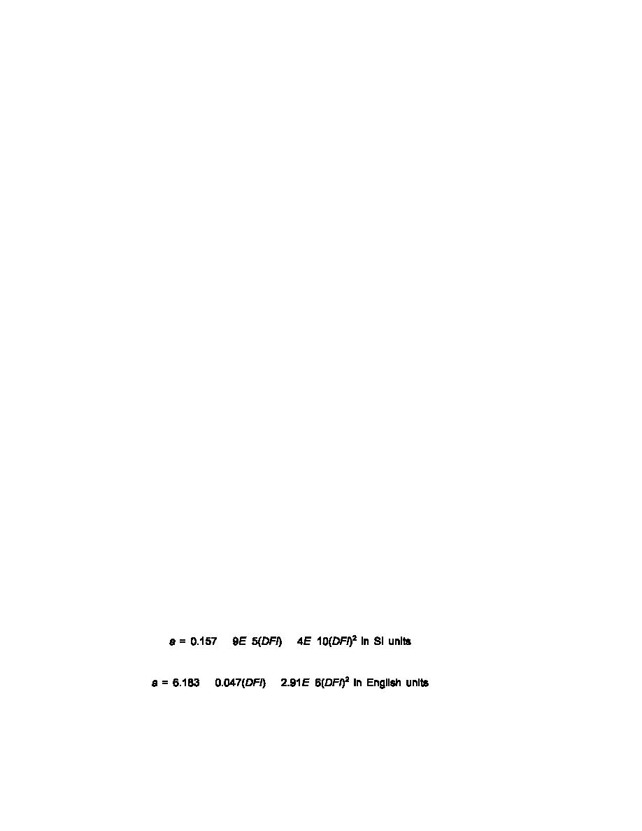
meters for SI units and inches for English units can also be estimated from the following equations:
(1) For ( = 2,160 kg/m3 (135 lb/ft3) and T = 3 percent,
(20-4)
%
&
&
&
(20-5)
%
&
&
(2) For ( = 2,160 kg/m3 (135 lb/ft3) and T = 7 percent,
20-7


 Previous Page
