2. STRESSES IN FLEXIBLE PAVEMENTS.
a. Single Wheels. Distribution of vertical stresses under a surface load
has a bell-shaped pattern. Stresses are at a minimum directly beneath the
wheel, and decrease with increasing depth. See NAVFAC DM-7 and NAVFAC DM-21
for stress distribution in soils.
b. Dual Wheels. When dual wheels support the same total load as a single
wheel, pavement stresses are reduced. At shallow depth, stresses are caused
principally by individual wheels acting singly, and are at a maximum beneath
the center of each wheel. At greater depths, stresses are at a maximum midway
between wheels, and approximate the stress caused by a single wheel supporting
the total load. Thus stresses in pavement are determined principally by
individual wheel loads, and especially by tire pressure, whereas required
total thickness of pavement, base, and subbase are determined principally by
total load.
c. Stress Repetition. The effects of stress repetition arc considered in
the design procedures by the concepts of equivalent 18 kip axle loads and the
DI. Although flexible pavements may sustain limited applications of a heavy
load, they may distort or fail under a high number of repetitions of the same
load.
3. THICKNESS DESIGN PROCEDURES. Use the following procedures for the design of
flexible pavements:
a. Design Index. Determine the DI using the procedures of Section 3.
b. Subgrade CBR. From Section 4, determine the design subgrade CBR.
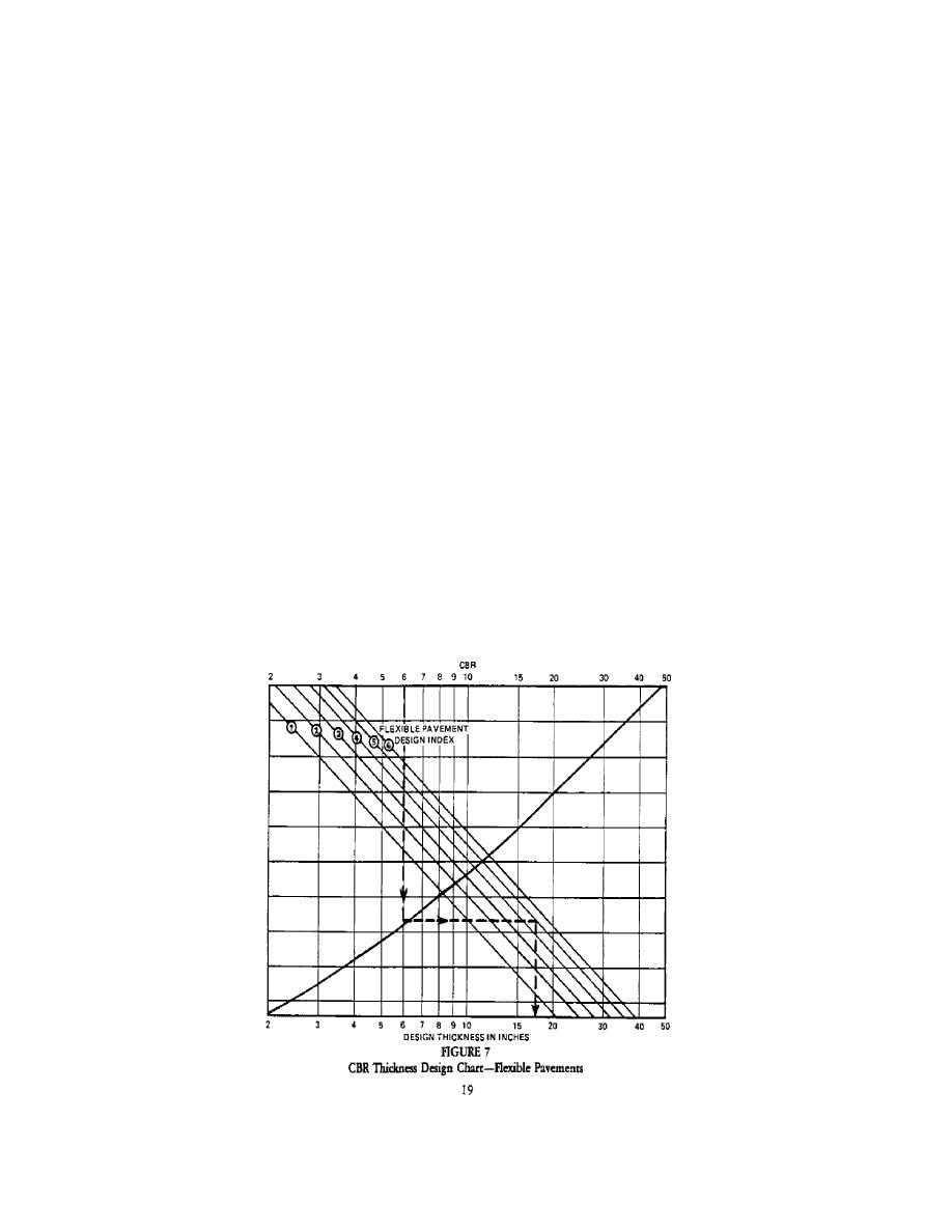
c. Total Thickness. Determine the total thickness of pavement required from
the design curve, Figure 7. Enter the design curve with the subgrade CBR,
proceed vertically to the ''break line," then horizontally to the DI, and
vertically to the design thickness.


 Previous Page
