TM 5-814-3/AFM 88-11, Volume III
(6) Mound length and width:
D%E
%F%H3
End slopes (K) = mound depth at center 3:1 slope =
2
= 1 % 2.25 % 1.00 % 2.0 3
2
= 13.8*, use 15*
Upslope width (J) = mound depth at upsiope edge 3:1 slope slope correction (table 6-2)
= (D + F + G) 3 .875
= (1.00 + 1.00 + 1.00) 3 .875
= 7.88, use 8.
Downslope width (I) = mound depth at lower edge 3:1 slope correction
= (E + F + G) 3 1.18
= (2.25 + 1.00 + 1.00) 3 1.18
= 15.04 ft, use 15 ft.
Mound length (L) = B = 2K = 60 + 2(15) = 90 ft.
Mound width (W) = I + A + J = 15 + 2(10) + 5 + 8 = 48 ft.
(7) Calculate basal area: On a sloping site, the basal area is that area under the slope of the bed; while
on level sites, the whole area of the mound may be used. Since this is a sloped area:
Basal area (BA) = Bx (A + I) = 60 [)2 10) + 5 + 15] = 2,400 ft2.
Basal area required (BAR) = daily flow infiltration capacity of soil.
Typical design loading rates are:
Percolation Rates
3-29 min/in
1.2 gal/ft2/day
30-60 min/in
0.75 gal/ft2/day
60-120 min/in
0.24 gal/ft2/day
Therefore, BAR = 900 gal/day 0.74 gal/ft2/day = 666.
Since BA< BAR, the slopes could be shortened. However, if slope is cut to 2:1, erosion may set in.
Therefore, size is acceptable at 2,400 ft2 since this figure is conservative by a factor of 4.
(8) Distribution system: For this size system, manifold pipe should be 2"; laterals, 1" PVC. The
manifold pipe should run from the pumping chamber (or dosing siphon) to the center of the mound to an
"elbow" and then through a "reducer" (from 2" to 1"), thence through a "tee" to the 6 lateral distribution
pipes below. The manifold pipe may be run above or below the beds but, in either case, must be designed
so that wastewater will drain from the laterals and the manifold between doses.
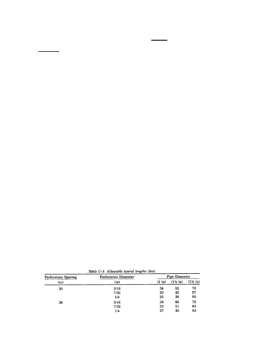
Table C-5 is used to determine perforation spacing and pipe diameter. In this case, laterals of 1-in
PVC are 30 ft long so that a 30-in spacing of 7/32-in holes is chosen.
C-44


 Previous Page
