TM 5-814-3/AFM 88-11, Volume III
(3) Fine screen with openings inch wide or smaller.
b. Design basis. Screens will be located where they are readily accessible. An approach velocity of 2 feet
per second, based on average flow of wastewater through the open area, is required for manually cleaned bar
screens. For a mechanically cleaned screen, the approach velocity will not exceed 3.0 feet per second at
maximum flows.
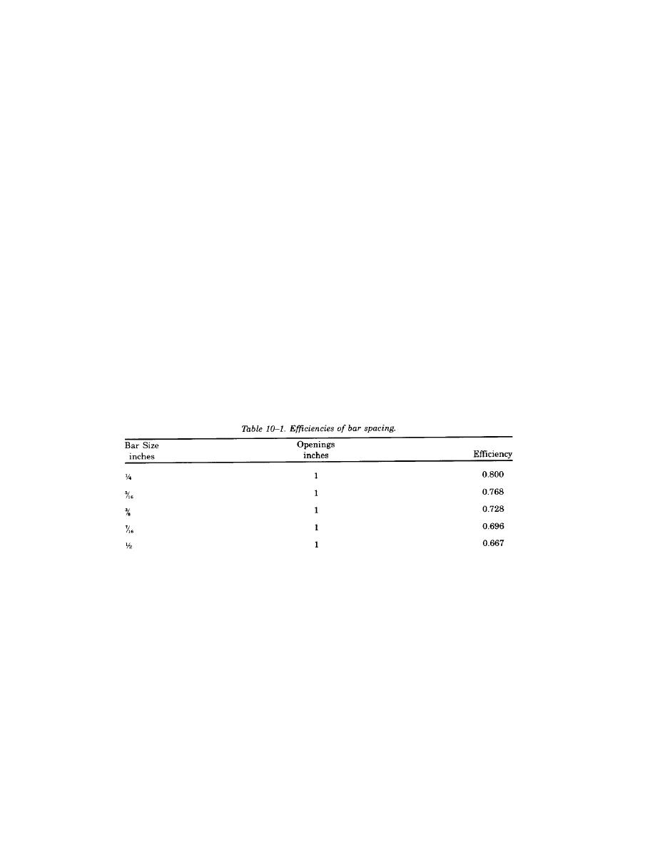
(1) Bar spacing. Clear openings of 1 inch are usually satisfactory for bar spacing, but to 1-inch
openings may be used. The standard practice will be to use 5/16-inch x 2-inch bars up to 6 feet in length and
3/8-inch x 2-inch or 3/8-inch x 2-inch bars up to 12 feet in length. The bar will be long enough to extend
above the maximum sewage level by at least 9 inches.
(3) Size of screen channel. The maximum velocity through the screen bars, based on maximum normal
daily flow, will be 2.0 feet per second. For wet weather flows or periods of emergency flow, a maximum
velocity of 3.0 feet per second will be allowed. This velocity will be calculated on the basis of the screen
being entirely free from debris. To select the proper channel size, knowing the maximum storm flow and the
maximum daily normal flow, the procedure is as follows: the sewage flow (million gallons per day) multiplied
by the factor 1.547 will give the sewage flow (cubic feet per second). This flow (in cubic feet per second)
divided by the efficiency factor obtained from table 10-1 will give the wet area required for the screen
channel. The minimum width of the channel should be 2 feet and the maximum width should be 4 feet. As
a rule, it is desirable to keep the sewage in the screen channel as shallow as possible in order to keep down
the head loss through the plant; therefore, the allowable depth in the channel may be a factor in determining
the size of the screen. In any event, from the cross-sectional area in the channel, the width and depth of the
channel can be readily obtained by dividing the wet area by the depth or width, whichever is the known
quantity.
(3) Velocity check. Although screen channels are usually designed on the basis of maximum normal
flow or maximum storm flow, it is important to check the velocities which would be obtained through the
screen for minimum or intermediate flows. The screen will be designed so that, at any period of flow, the
velocities through the screen do not exceed 3 feet per second under any flow condition.
(4) Channel configuration. Considerable attention should be given to the design of the screen channel
to make certain that conditions are as favorable as possible for efficient operation of the bar screen. The
channel in front of the screen must be straight for 25 feet. Mechanical screens with bars inclined at an angle
of 15 degrees from the vertical will be installed.
(5) Screenings. The graph shown in figure 10-2 will be used to predict the average amount of
screenings that will be collected on the bar screen. The information required to make this estimate is flow and
bar spacing. Grinding of the screenings (and returning them to the wastewater flow), incineration, and
landfilling are satisfactory methods for disposal of the screenings.
10-3


 Previous Page
