TM 5-820-1/AFM 88-5, Chap 1
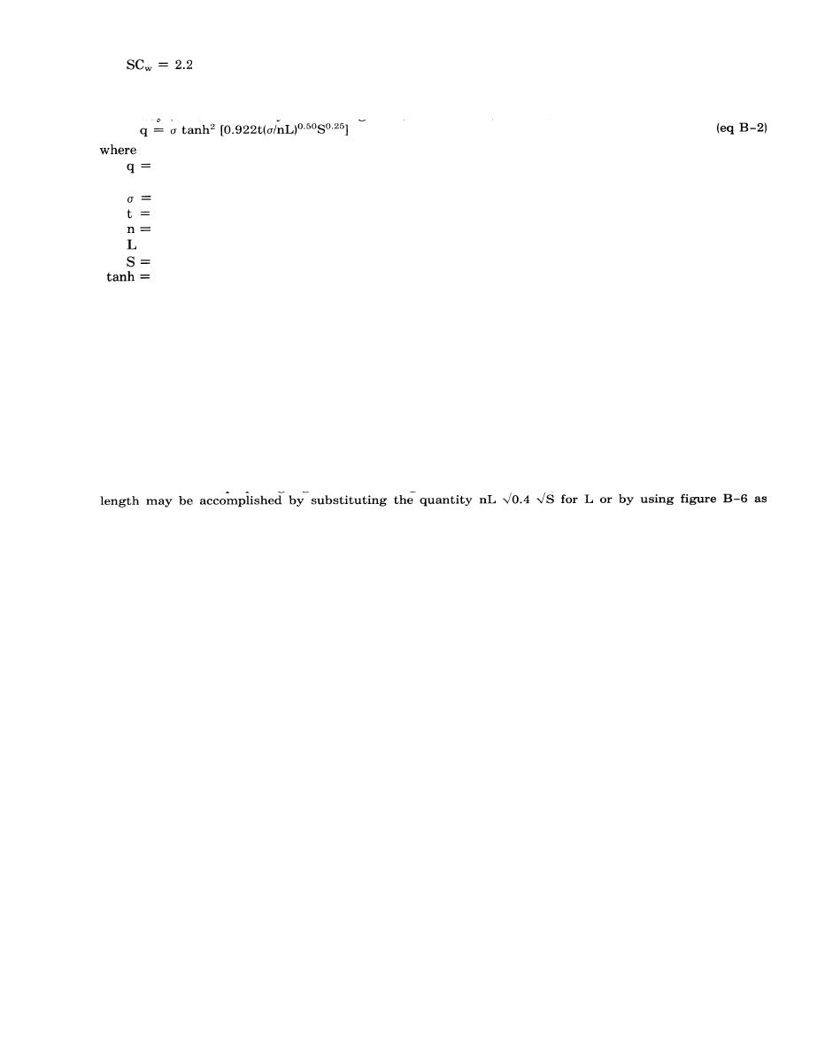
d. Overland flow. The rate of overland flow to be expected from a continuous and uniform rate of
rainfall excess, or rate of supply, can be determined from equation B 2 as interpreted by G. A.
Hathaway (American Society of Civil Engineers, Transactions, Vol 110):
rate of overland flow at the lower end of an elemental strip, inches per hour or cubic feet per
second per acre.
rate of supply or intensity of rainfall excess, inches per hour.
time, or duration, from beginning of supply, minutes.
coefficient of roughness of the surface.
effective length of overland, or channel flow, feet.
slope of the surface (absolute, that is, 1 percent = 0.01).
hyperbolic tangent.
(1) The curves shown in figures B-2 through B-4 were computed using equation B-2, assuming n
= 0.40 and S = 0.01. The overland flow curves are the hydrography that would result from continuous
and uniform rates of rainfall-excess or rates of supply. From the curves, hydrography can be developed
for any selected duration and rate of rainfall-excess by the procedure shown in figure B-5. Hydrography
1 and 1-A in figure B-5 represent rates of runoff under given conditions assuming supply continues
indefinitely. However, by lagging the hydrography for a selected period of rainfall-excess, tr (20 minutes
in this example), and subtracting runoff in hydrography 1-A from hydrography 1, a hydrography can be
obtained that represents the runoff pattern for the selected period of rainfall-excess (hydrography 2 in the
example).
(2) Overland flow curves may be used for surfaces having other coefficients of roughness or slopes
by using, instead of actual length of the flow involved, a hypothetical length that is greater or less than
the actual by a sufficient amount to compensate for the difference between the correct values of n and S
and those used in preparing figures B-2 through B4. The necessary conversions to get an effective
explained in paragraph B2.
B-2. Effective length.
L
a. General. In equation B 2, the effective length, L, represents the length of overland flow, measured
in a direction parallel to the maximum slope, from the edge of the drainage area to a point where runoff
has reached a defined channel or pending basin. In large drainage areas, considerable channelized flow
will occur under design-storm conditions. Investigation of many runoff records for watersheds has
indicated that by modifying the actual length, satisfactory reproduction of runoff hydrography may be
obtained regardless of channelization of flow. The values for L are determined by summing the length of
channel flow and the length of overland flow after each has been reduced to an effective length for n =
0.40 and S = 1.0 percent by means of figure B-6. The length of channel flow is measured along the
proposed collecting channel for that section in which appreciable depth of flow may be reasonably be
expected to occur during the design storm. Length of overland flow is the average distance from the end
of the effective channel or from the drain inlet to the edge of the drainage area, measured in the
direction of flow as indicated on the proposed grading plans. Airfield and heliport grading is such that
overland flow will normally channelize in distances of 600 feet or less, although this distance may be
exceeded. Whenever the distance is exceeded, the actual length may be divided by a number so that the
quotient conveniently falls on the horizontal axis of graph A on figure B-6. The length derived from
graph B on the figure would then be multiplied by this same number to determine the final effective
length. Typical values of the coefficient of roughness, n, for use in determining effective length of
overland flow are given in table B-2. TM 5-8203/AFM 88-5, Chap. 3 gives additional n values for
turfed channels. For example, to find the effective length of overland flow for an actual length of 900
feet on a sparse grass ground cover where n = 0.20, and the overall slope is 0.7 percent, use the
following procedure. Divide the 900-foot actual length by 2 and enter graph A of figure B-6 with 450
feet on the horizontal axis. Project a line vertically upward until it intersects the coefficient of roughness
line; proceed horizontally to the intersection of the slope line equal to 0.7 percent on graph B, and
proceed vertically down to obtain a length of 275 feet, which must be multiplied by 2, resulting in a total
effective length of overland flow of 550 feet.
B-3


 Previous Page
