TM 5-818-8/AFJMAN 32-1030
Table 6-1. Recommended Geotextile Mininmum Strength Re-
in case of UV protected and low UV susceptible
quirements.
polymer geotextiles. The geotextile should be
loosely laid, free of tension, folds, and wrinkles.
1
2
Type Strength Test Method
Class A
Class B
When used for streambank protection, where cur-
Grab Tensile
ASTM D
4632
90
200
rents acting parallel to the bank are the principal
Elongation (%)
ASTM D
4632
15
15
erosion forces, the geotextile should be placed with
Puncture
ASTM D
4833
80
40
the longer dimension (machine direction) in the
ASTM D
4533
Tear
50
30
ASTM D
3884
Abrasion
55
25
direction of anticipated water flow. The upper
ASTM D
4632
Seam
80
180
strips of the geotextile should overlap the lower
Burst
ASTM D
3786
320
140
strips (fig 6-3). When used for wave attack or cut
1
Fabrics are used under conditions more severe than Class B
and fill slope protection, the geotextile should be
such as drop height less than 3 feet and stone weights should
placed vertically down the slope (fig 6-3), and the
not exceed 250 pounds.
upslope strips should cover the downslope strips.
`
Fabric is protected by a sand cushion or by zero drop height.
Stagger the overlaps at the ends of the strips at
b. Construction Considerations.
least 5 feet. The geotextile should be anchored at
(1) Site preparation. The surface should be
its terminal ends to prevent uplift or undermining.
cleared of vegetation, large stones, limbs, stumps,
For this purpose, key trenches and aprons are used
trees, brush, roots, and other debris and then
at the crest and toe of the slope.
graded to a relatively smooth plane free of obstruc-
tions, depressions, and soft pockets of materials.
(3) Overlaps, seams, securing pins. Adjacent
(2) Placement of geotextiles. The geotextile is
geotextile strips should have a minimum overlap
unrolled directly on the smoothly graded soil
of 12 inches along the edges and at the end of
surface. It should not be left exposed to UV
rolls. For underwater placement, minimum over-
deterioration for more than 1 week in case of
lap should be 3 feet. Specific applications may
untreated geotextiles, and for more than 30 days
require additional overlaps. Sewing, stapling, heat
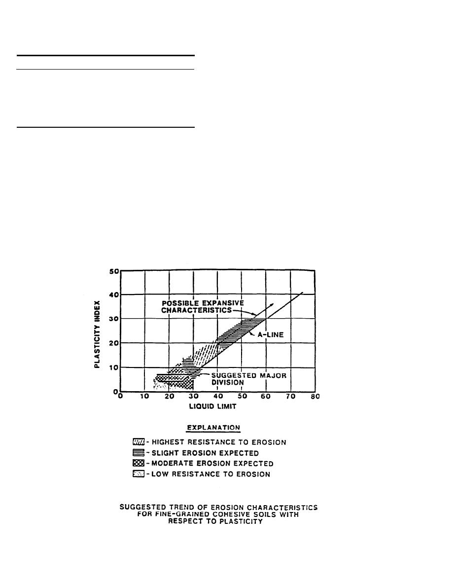
Figure 6-1. Relationship between Atterberg Limits and Expected Erosion Potential.
6-2


 Previous Page
