EI 02G001
CEMP-E
01 July 1997
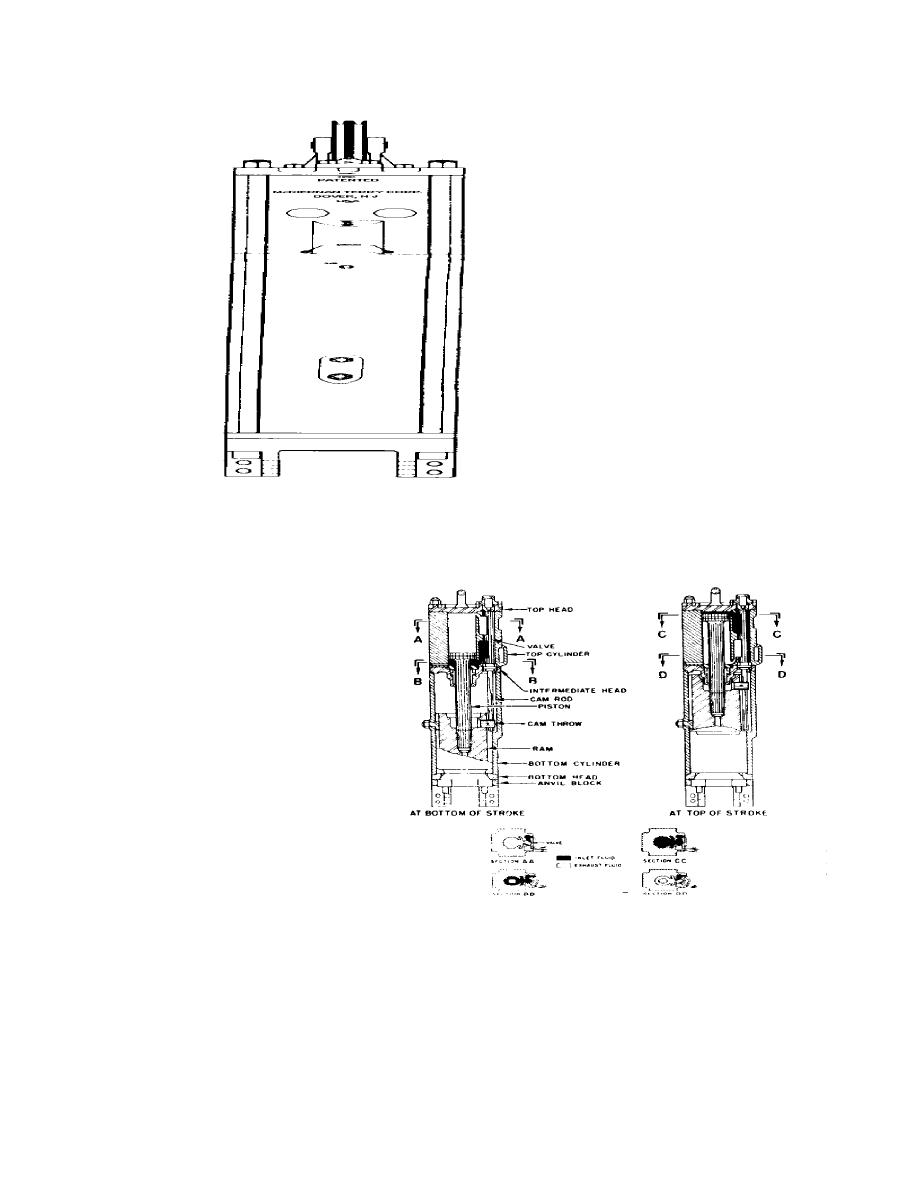
Figure 3-7a. Typical double-acting air/stream hammer.
The ram carries a rigidly connected cam throw (some
double acting hammers use a fluid valve) which
engages a camrod suspended in the intermediate
head of the hammer. In operation, the motive fluid
first enters the inlet port and flows through the lower
opening of the valve to the underside of the piston.
The top opening of the valve completes a path from
the topside of the piston to the exhaust port. As the
fluid lifts the piston, thus lifting the ram, the lugs of the
cam throw slide past the edges of the cam rod until, at
the top of the stroke, they engage a spiral portion of
the cam rod, causing it to rotate. The valve connected
to the top of the cam rod also rotates, allowing the inlet
motive fluid on the underside of the piston to escape
through the exhaust port. The ram then falls, its
velocity increased by the fluid pressure on the top of
the piston. The cam throw lugs slide down where
another spiral portion of the cam rode is engaged. The
cam rod rotates; rotating the valve to the original
position, and the motive fluid path reverses.
Figure 3-7b. Interior view of air/ateam hammer.
3-32


 Previous Page
