EI 02C097
01 Jul 97
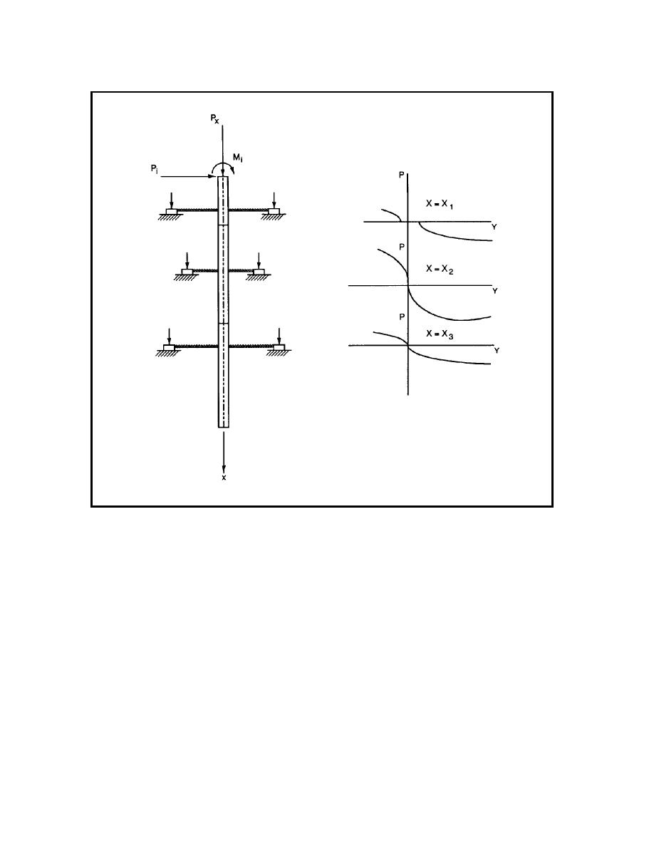
Figure 4-1. Model of pile under lateral loading with
p-y curves
in Figure 4-3. Two slices of soil are indicated; the element A
is near the ground surface and the element B is several
(a) Ultimate resistance to lateral movement. With regard
to the ultimate resistance at element A in Figure 4-3, Figure 4-5
diameters below the ground surface. Consideration will be
given here to the manner in which those two elements of soil
shows a wedge of soil that is moved up and away from a pile.
react as the pile deflects under an applied lateral load. Figure 4-
The ground surface is represented by the plane ABCD, and soil
4 shows a p-y curve that is conceptual in nature. The curve is
in contact with the pile is represented by the surface CDEF. If
plotted in the first quadrant for convenience and only one branch
the pile is moved in the direction indicated, failure of the soil in
is shown. The curve properly belongs in the second and fourth
shear will occur on the planes ADE, BCF, and AEFB. The
horizontal force Fp against the pile can be computed by summing
quadrants because the soil response acts in opposition to the
deflection. The branch of the p-y curves 0-a is representative of
the horizontal components of the forces on the sliding surfaces,
the elastic action of the soil; the deflection at point a may be
taking into account ote gravity force on the wedge of soil. For a
small. The branch a-b is the transition portion of the curve. At
given value of H, it is assumed that the value of the horizontal
point b the ultimate soil resistance is reached. The following
force on the pile is
paragraphs will deal with the ultimate soil resistance.
4-2


 Previous Page
