TM 5-820-4/AFM 88-5. Chap. 4
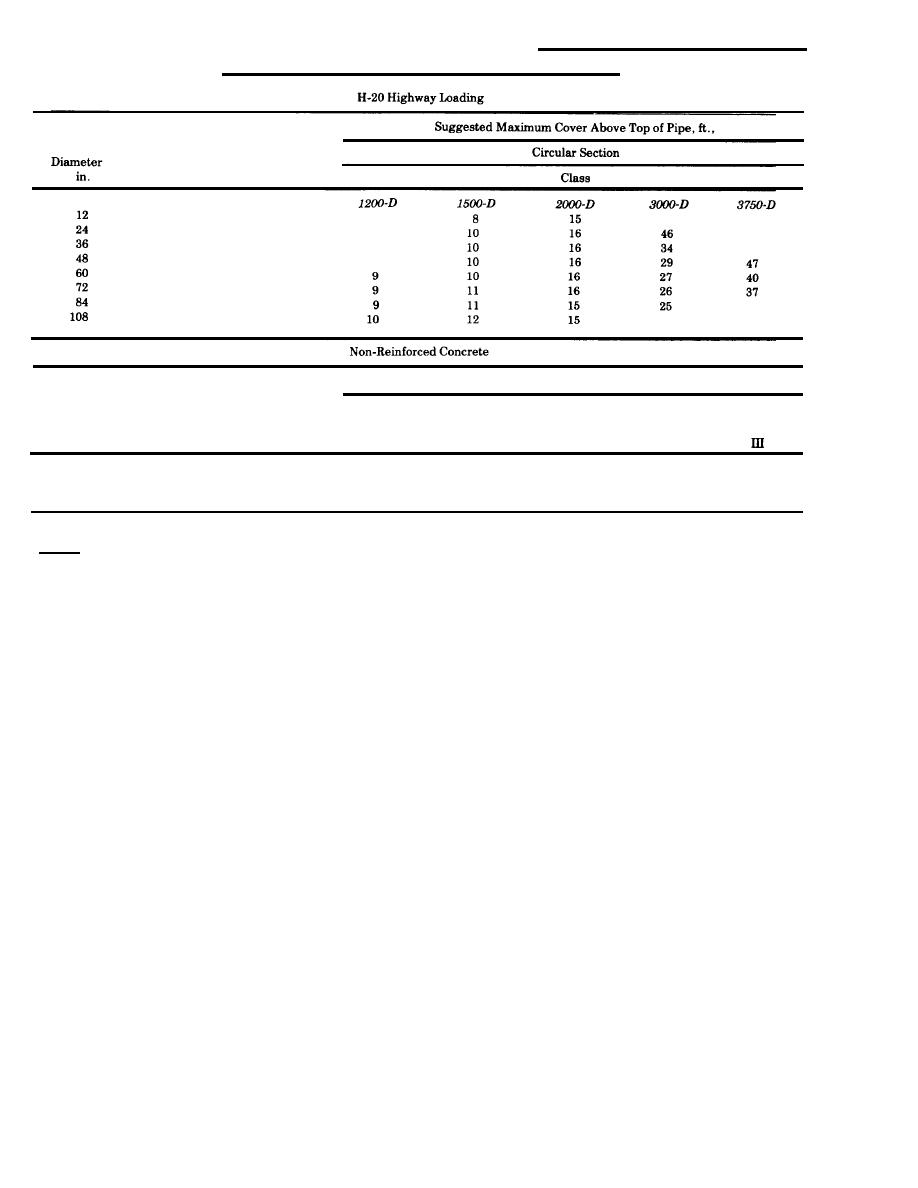
Table C-2. Suggested Maximum Cover Requirements for Concrete Pipe
Reinforced Concrete
Suggested Maximum Cover Above Top of Pipe, ft.
Circular Section
Diameter
in.
II
I
17
14
12
14
13
14
24
13
12
12
36
9
U.S. Army Corps of Engineers
Notes:
1. The suggested values shown are for average conditions and are to be considered as guidelines only for dead load plus H-20
live load.
2< Soil conditions, trench width and bedding conditions vary widely throughout varying climatic and geographical areas.
3! Calculations to determine maximum cover should be made for all individual pipe and culvert installations underlying roads,
streets and open storage areas subject to H-20 live loads. Cooper E-80 railway loadings should be independently made.
4. Cover depths are measured from the bottom of the subbase of pavements, or the top of unsurfaced areas, to top of pipe.
5. Calculations to determine maximum cover for Cooper E-80 railway loadings are measured from the bottom of the tie to the
top of the pipe.
6. "D" loads listed for the various classes of reinforced-concrete pipe are the minimum required 3-edge test loads to produce
ultimate failure in pounds per linear foot of interval pipe diameter.
7. Each diameter pipe in each class designation of non-reinforced concrete has a different D-load value which increases with
wall thickness.
8. If pipe produced by a manufacturer exceeds the strength requirements established by indicated standards, then cover
depths may be adjusted accordingly.
9. See table C-9 for suggested minimum cover requirements.
Change 1 C-3
tions; each condition deviating from the average
pipe, corrugated-steel pipe, structural-plate-alu-
condition should be analyzed separately. Where
minum-alloy pipe, and structural-plate-steel pipe.
warranted by design analysis the suggested maxi-
The different sizes and materials of conduit and pipe
mum cover may be exceeded.
have been selected to allow the reader an apprecia-
tion for the many and varied items which are com-
mercially available for construction purposes. The
C-6. Classes of bedding and installation. Figures
cover depths listed are suggested only for average
C-1 through C-5 indicate the classes of bedding for
bedding and backfill conditions. Deviations from
conduits. Figure C-6 is a schematic representation
average conditions may result in significant mini-
of the subdivision of classes of conduit installation
mum cover requirements and separate cover analy-
which influences loads on underground conduits.
ses must be made in each instance of a deviation
Change 1 C-3
from average conditions. Specific bedding, backfill
--
and trench widths may be required in certain loca-
Change 1 C-3


 Previous Page
