TM 5-820-3/AFM 88-5, Chap. 3
1.2 and less than 2.0 if supercritical to prevent flow
capacities of channels that will satisfy the desired
instabilities and excessive wave heights. It should
conditions. The calculated values of discharge and
also be designed to have a depth-to-width ratio as
channel widths can be plotted on log-log paper as
near 0.5 (the most efficient hydraulic rectangular
shown in figure D-7 to determine the respective
cross section) as practical depending upon the local
relations for supercritical rectangular channels with
conditions of design discharge, maximum depth of
a depth-to-width ratio of 0.5, a slope of 0.01 foot
flow permissible, and commensuration of a slope
per foot, and a Manning's n of 0.015. Figure D-7
with that of the local terrain.
may then be used to select a channel width of 7.5
(12)
For example, assume that a paved
feet for conveyance of the design discharge of 400
rectangular channel is to be provided with a
cubic feet per second. The exact value of the
constraining parameter SB1/3/n2 can be calculated to
Manning's n = 0.015 and a slope of 0.01 foot per
foot (average slope of local terrain) for conveyance
be 87 and used in conjunction with a D/B ratio of
of the remaining constraining parameters, Q%gB5 =
of a design discharge of 400 cubic feet per second
0.5 and figure D-6 to obtain corresponding values
at supercritical conditions. A depth-to-width ratio
of 0.5 is desired for hydraulic efficiency and a
0.48 and F = 1.4, required to satisfy all of the
Froude number of flow between 1.2 and 2.0 is
dimensionless relations shown in figure D-6. The
desired for stable supercritical flow. The range of
actual discharge capacity of the selected 7.5-foot-
values of the parameter SB1/3]/n2(70-180) required
wide channel with a depth of flow equal to 3.75
to satisfy the desired D/B and range of Froude
feet can be calculated based on these relations to
number of supercritical flow can be determined
ensure the adequacy of the selected design. For
parameter %gB5 (0.44-0.68) can also be determined
from figure D-6. Corresponding values of the
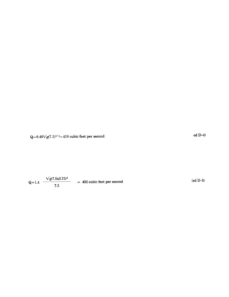
example, based on the magnitude of a discharge
parameter equal to 0.48, the channel should convey
from figure D-6 for calculation of the discharge
419 cubic feet per second:
Similarly, based on the magnitude of a Froude
number of flow equal to 1.4, the channel should
convey a discharge of 432 cubic feet per second:
Obviously, the capacity of the 7.5-foot-wide chan-
nel is adequate for the design discharge of 400
cubic feet per second.
D-7


 Previous Page
