TM 5-820-3/AFM 88-5, Chap. 3
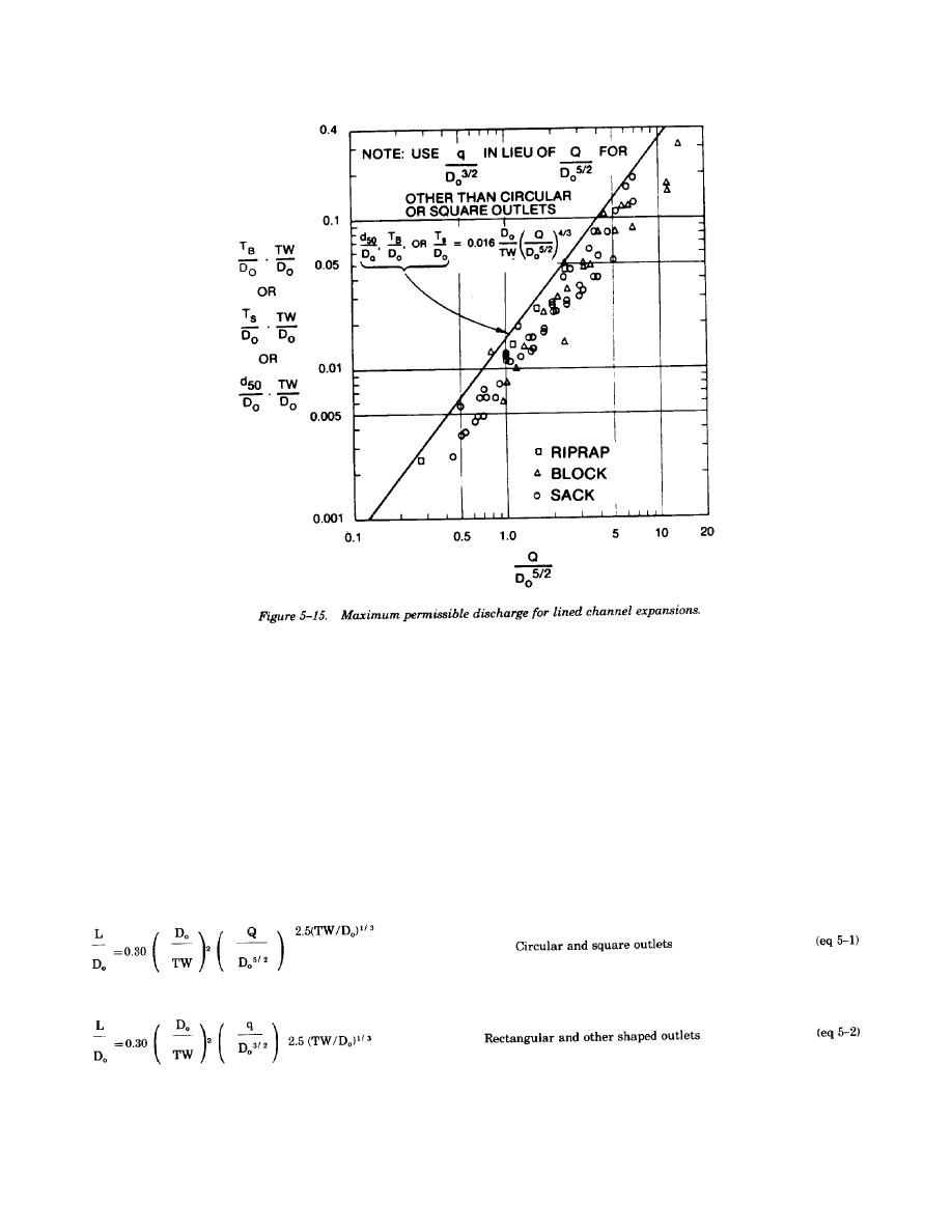
e. The maximum discharge parameters, Q/Do5/2
f. The simplest form of energy dissipator is the
or q/Do3/2, of various schemes of protection can be
flared outlet transition. Protection is provided to
calculated based on the above information; com-
the local area covered by the apron, and a portion
parisons relative to the cost of each type of protec-
of the kinetic energy of flow is reduced or convert-
tion can then be made to determine the most prac-
ed to potential energy by hydraulic resistance pro-
tical design for providing effective drainage and
vided by the apron. A typical flared outlet transition
erosion control facilities for a given site. There will
is shown in figure 5-16. The flare angle of the walls
be conditions where the design discharge and
should be 1 on 8. The length of transition needed
economical size of conduit will result in a value of
for a given discharge conduit size and tailwater
the discharge parameter greater than the maximum
situation with the apron at the same elevation as the
value permissible thus requiring some form of
outlet invert (H = 0) can be calculated by the
energy dissipator.
following equations.
Recessing the apron and providing an end sill will
not significantly improve energy dissipation.
5-17


 Previous Page
