TM 5-820-1/AFM 88-5, Chap 1
B-5. Drain-inlet and drain capacities.
a. Determination of drain-inlet capacities without pending. From figures B-7 through B-14, select
the supply curve number corresponding to the weighted standard supply curve determined previously.
for the individual inlet drainage area can be read directly from the graph for the given value of effective
length. If figure B-15 is used, the same data can be obtained by following the procedure described in
paragraph B-3c.
(1) To obtain the maximum rate of runoff at a given point in a drainage system, during a supply
of uniform intensity, the storm must continue long enough to produce the maximum rate of runoff into
each upstream inlet and to permit the inflow to travel through the drain from the "critical inlet" to the
point of design. "Critical inlet" is defined as the upstream inlet from which the critical duration of
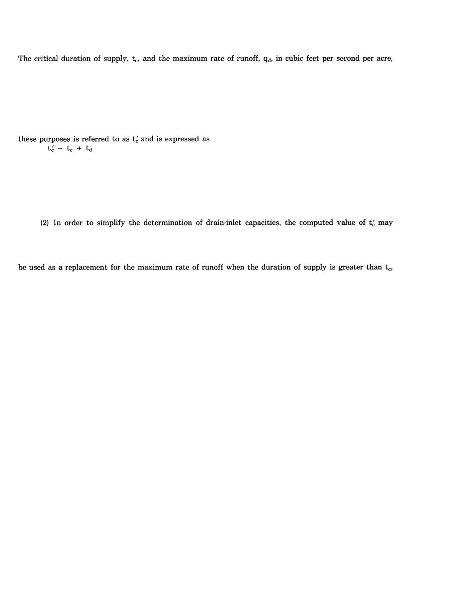
supply causes the maximum runoff to the point of design. The critical duration of supply necessary for
(eq B-4)
where tC is the duration of supply that would provide the maximum design-storm runoff from the area
tributary to the critical drain inlet, and td is the time required for water to flow from the critical drain
inlet to the point of design. The critical drain inlet normally may be assumed to be the inlet located the
greatest distance upstream from the given point. Care should be taken to check whether tC to an inlet
along a drainage line exceeds the time required for water falling on a more distant area to reach this
same inlet. Problems which arise in this regard must be investigated individually to determine under
what conditions of time and flow the maximum volume of water can be expected at the point of design.
be rounded off to the nearest 5 minutes. Inspection of figures B-7 through B-14 will disclose that for
large values of effective length and low values of supply curves the maximum rate of runoff is approxi-
mately constant after tC duration of supply. In order to facilitate design computations, the drain-inlet ca-
pacity values, qd, obtained from the O storage capacity line of diagram A of figures B-20 and B-21 should
when the values of effective length are large, and when low values of the supply curve are in effect.
b. Determination of drain-inlet capacities with temporary pending. From figures B-17 through B-21,
select the graph corresponding to the effective length and determine the drain-inlet capacity from the
given standard supply curve value and maximum permissible pending. In a drainage system where
pending is used, the maximum rate of flow at any given point in the drainage system may be
determined, in most cases, by the simple addition of the peak discharges for the upstream inlets based
on drain-inlet capacities. This procedure is justified in view of the prolonged period where temporary
pending takes place as shown in figure B-16. Curve 4 in figures B-17 through B-21 represents the
minimum drain-inlet capacities that are considered desirable, regardless of the volume of flooding
exceeding allowable limits. The drain-inlet capacities represented by curve 4, in cubic feet per second per
acre of drainage area, are equal to the rates of supply corresponding to durations of 4 hours on the
respective standard supply curve given in figure 2. If the drain-inlet capacity indicated by curve 4 is
adopted in a particular case, some storage may result in the pending basin during all storms less than 4
hours in duration that produce supply rates corresponding to the given standard supply curve. The
proper criteria to be followed in estimating minimum drain-inlet capacities depend largely on the extent
of drainage desired and the characteristics of the soil involved.
c. Computation of pipe sizes. The size and gradient of storm drain required to discharge
design-storm runoff may be determined by use of Manning's formula presented in nomograph form in
figures B-22 through B-25. Storm drains will have a minimum diameter of 12 inches to lessen
possibilities of clogging. Design of drain-inlet facilities is discussed in TM 5-820-3/AFM 88-5, Chap. 3.
(1) For conditions of instantaneous runoff the hydraulic gradient will be kept at the top of the
pipe. Where temporary pending is proposed, considerable saving in pipe sizes may be accomplished by
designing the pipeline under pressure, provided undesirable backflow does not result in some critical
areas.
(2) Where flooding from a temporary pending area due to rates of supply greater than design will
cause a hazard to the adjacent areas, special provisions must be made to assure adequate control. An
auxiliary drainage system or a diversionary channel to another inlet or pending area is a method that
has been used successfully. The designer must consider each case individually to arrive at the most
economical solution to provide the desired results.
B-28


 Previous Page
