TM 5-813-9
CHAPTER 4
4-1. Headloss and System Curves
system. The pump discharge head will be the
required pressure needed at the point of connection
a. General, The location and required capacity
to the distribution system plus the pumping station
of a potable water pumping installation will be
and pump discharge and suction piping head loss.
determined from a hydraulic network analysis of the
Example problems and information on friction loss
distribution system. Pumping requirements for
in suction and discharge piping will be found in the
various design conditions at one or several loca-
Hydraulic Institute Engineering Data Book. A
tions can be simulated for varying flow rates over
design analysis will be prepared to show head loss
extended periods of time by use of computer
and friction calculations for present and future
programs. Refer to appendix B for available com-
demands.
puter programs. Based on this information, the
b. System head curves. In every case where
pump station including suction and discharge piping
liquid is transported from a point A to a point B,
systems will be designed. To make an accurate
there is a friction loss through the piping system
determination of the head requirements, a system
between the two points, and there may be an
head curve must be derived depicting calculated
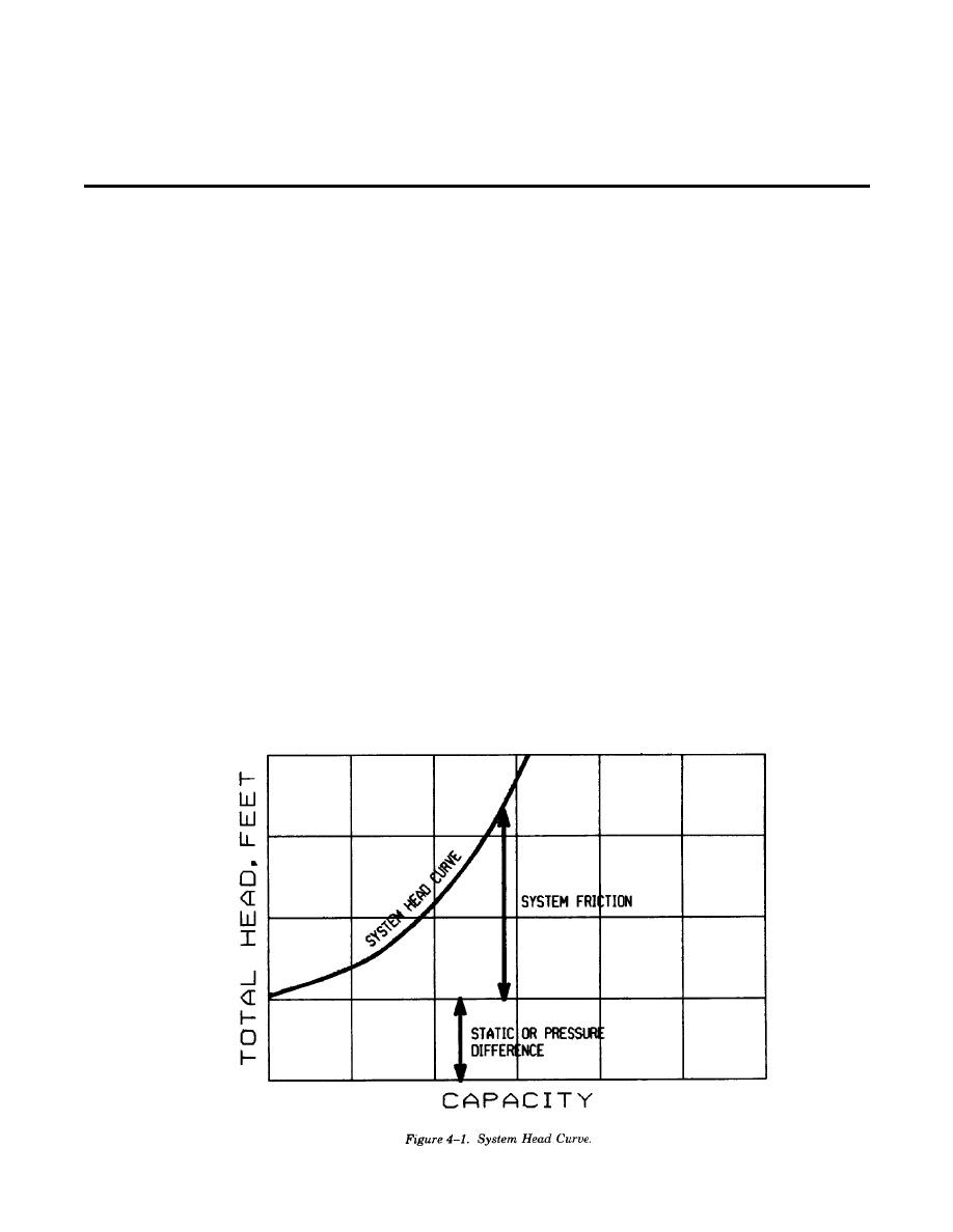
elevation or pressure differential. A simplified
losses through the system for various pumping
system head curve is shown in figure 4-1.
rates. A schematic should be drawn showing con-
After analyzing the actual system to determine its
figuration and size of all piping including valves and
requirements, it is good practice to plot the system
fittings. Information on system headloss calcu-
head curve for any flow rate from 0 to beyond the
lations can be found in TM 5-813-5. Pumps at the
pump station required peak capacity knowing that
pump stations will be sized to handle individually
the friction loss will be 0 at 0 gum flow.
and in combination the maximum projected daily
c. Pump selections. With the system defined,
consumption, the peak hourly rate plus fire load
pumps will be selected. The point of intersection
demand, and the estimated minimum hourly rate at
between the pump performance curve and the
some future date. Refer to appendix C for a case
system head curve represents the capacity at which
study for adding pumps to an existing distribution
4-1


 Previous Page
