TM 5-818-8/AFJMAN 32-1030
with the soil and geotextile chosen, then the
as the average strain, then the maximum strain
which would occur is 5 percent.
embankment side slopes must be flattened, or
additional berms may be considered. Most high-
e. Potential Embankment Rotational Displace-
strength geotextiles exhibit a fairly high soil-
ment. It is assumed that the geotextile ultimate
geotextile friction angle that is equal to or greater
tensile resistance is instantaneously developed to
than 30 degrees, where loose sand-size fill material
prevent rotational slope/foundation failure and is
is utilized. Assuming that the embankment sliding
inherently included in the slope stability limit
equilibrium analysis. But for the geotextile to
analysis results in the selection of a geotextile
develop tensile resistance, the geotextile must
that prevents embankment fill material from slid-
strain in the vicinity of the potential failure plane.
ing along the geotextile interface, then the result-
To prevent excessive rotational displacement, a
ant force because of lateral earth pressure must be
high-tensile-modulus geotextile should be used.
less than the tensile strength at the working load
The minimum required geotextile tensile modulus
of the geotextile reinforcement to prevent spread-
to limit or control incipient rotational displace-
ing or tearing. For an FS of 1, the tensile strength
ment is the same as for preventing spreading
would be equal to the resultant of the active earth
failure.
pressure per unit length of embankment. A mini-
f. Longitudinal Geotextile Strength Require-
mum FS of 1.5 should be used for the geotextile to
ments. Geotextile strength requirements must be
prevent embankment sliding. Therefore, the mini-
evaluated and specified for both the transverse
mum required tensile strength to prevent sliding
and longitudinal direction of the embankment.
is:
Stresses in the warp direction of the geotextile or
= 1.5 P A
(eq 4-6)
longitudinal direction of the embankment result
from foundation movement where soils are very
where
= minimum geotextile tensile strength.
soft and create wave or a mud flow that drags on
d. Embankment Spreading Failure Analysis.
the underside of the geotextile. The mud wave not
Geotextile tensile forces necessary to prevent lat-
only drags the geotextile in a longitudinal direc-
eral spreading failure are not developed without
tion but also in a lateral direction toward the
some geotextile strain in the lateral direction of
embankment toes. By knowing the shear strength
the embankment. Consequently, some lateral
of the mud wave and the length along which it
movement of the embankment must be expected.
drags against the underneath portion of the geo-
Figure 4-3 shows the geotextile strain distribution
textile, then the spreading force induced can be
that will occur from incipient embankment spread-
calculated. Forces induced during construction in
ing if it is assumed that strain in the embankment
the longitudinal direction of the embankment may
varies linearly from zero at the embankment toe
result from the lateral earth pressure of the fill
to a maximum value beneath embankment crest.
being placed. These loads can be determined by
Therefore, an FS of 1.5 is recommended in deter-
the methods described earlier where
mining the minimum required geotextile tensile
and
= 20
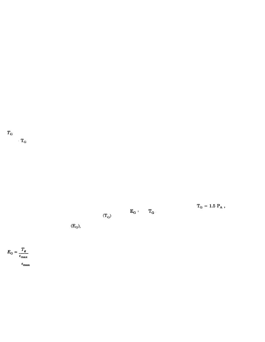
at 5 percent strain. The geotextile
modulus. If the geotextile tensile strength
strength required to support the height of the
determined by equation 4-6 is used to determine
embankment in the direction of construction must
the required tensile modulus
an FS of 1.5
also be evaluated. The maximum load during
will be automatically taken into account, and the
construction includes the height or thickness of
minimum required geotextile tensile modulus may
the working table, the maximum height of soil and
be calculated as follows:
the equipment live and dead loads. The geotextile
strength requirements for these construction loads
(eq 4-7)
must be evaluated using the survivability criteria
discussed previously.
where
= maximum strain which the geotex-
g. Embankment Deformation. One of the pri-
tile is permitted to undergo at the embankment
mary purposes of geotextile reinforcement in an
center line. The maximum geotextile strain is
embankment is to reduce the vertical and horizon-
equal to twice the average strain over the embank-
tal deformations. The effect of this reinforcement
ment width. A reasonable average strain value of
on horizontal movement in the embankment
2.5 percent for lateral spreading is satisfactory
spreading modes has been addressed previously.
from a construction and geotextile property stand-
One of the more difficult tasks is to estimate the
point. This value should be used in design but
deformation or subsidence caused by consolidation
depending on the specific project requirements
and by plastic flow or creep of very soft foundation
larger strains may be specified. Using 2.5 percent
materials. Elastic deformations are a function of
4-6


 Previous Page
