
TM 5-815-5/AFM 88-5, Chap 6/NAVFAC P-418
U.S. Army Corps of Engineers
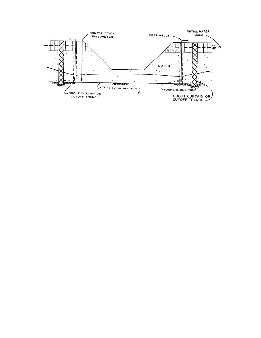
Figure 2-11. Grout curtain or cutoff trench around an excavation.
vation surrounded by a cofferdam. Excavations for
b. Factors controlling selection. Where foundations
deep shafts, caissons, or tunnels that penetrate strati-
must be constructed on soils below the groundwater
fied pervious soil or rock can generally best be dewa-
level, it will generally be necessary to dewater the ex-
tered with either a deep-well system (with or without
cavation by means of a deep-well or wellpoint system
an auxiliary vacuum) or a jet-eductor wellpoint system
rather than trenching and sump pumping. Dewatering
depending on the soil formation and required rate of
is usually essential to prevent damage to foundation
pumping, but slurry cutoff walls and freezing should
soils caused by equipment operations and sloughing or
be evaluated as alternative procedures. Other factors
sliding in of the side slopes. Conventional deep-well
relating to selection of a dewatering system are inter-
and wellpoint systems designed and installed by com-
panies specializing in this work are generally satisfac-
ference of the system with construction operations,
space available for the system, sequence of construc-
tory, and detailed designs need not be prepared by the
tion operations, durations of dewatering, and cost of
engineer. However, where unusual pressure relief or
dewatering requirements must be achieved, the engi-
the installation and its operation. Where groundwater
neer should make detailed analyses and specify the de-
lowering is expensive and where cofferdams are re-
watering system or detailed results to be achieved in
quired, caisson construction may be more economical.
Caissons are being used more frequently, even for
the contract documents. Where unusual equipment
small structures.
and procedures are required to achieve desired results,
they should be described in detail in the contract docu-
(2) Geologic and soil conditions. The geologic and
soil formations at a site may dictate the type of dewa-
ments. The user of this manual is referred to
tering or drainage system. If the soil below the water
paragraphs 6b, 14b, and 2f of Appendix III, TM
table is a deep, more or less homogeneous, free-drain-
5-818-4/AFM 88-5, Chapter 5, for additional discus-
sions of dewatering requirements and contract speci-
ing sand, it can be effectively dewatered with either a
conventional well or wellpoint system. If, on the other
fications. Major factors affecting selection of dewater-
hand, the formation is highly stratified, or the saturat-
ing and groundwater control systems are discussed in
ed soil to be dewatered is underlain by an impervious
the following paragraphs.
stratum of clay, shale, or rock, wellpoints or wells on
relatively close centers may be required. Where soil
excavations where the depth of water table lowering is
and groundwater conditions require only the relief of
small, can generally be dewatering most economically
artesian pressure beneath an excavation, this pressure
and safely by means of a conventional wellpoint sys-
relief can be accomplished by means of relatively few
tem. If the excavation requires that the water table or
deep wells or jet-eductor wellpoints installed around
artesian pressure be lowered more than 20 or 30 feet, a
and at the top of the excavation.
system of jet-eductor type wellpoints or deep wells
may be more suitable. Either wellpoints, deep wells, or
(a) If an aquifer is thick so that the penetration
of a system of wellpoints is small, the small ratio of
a combination thereof can be used to dewater an exca-
2-10

 Previous Page
