TM 5-852-4/AFM 88-19, Chap. 4
U. S. Army Corps of Engineers
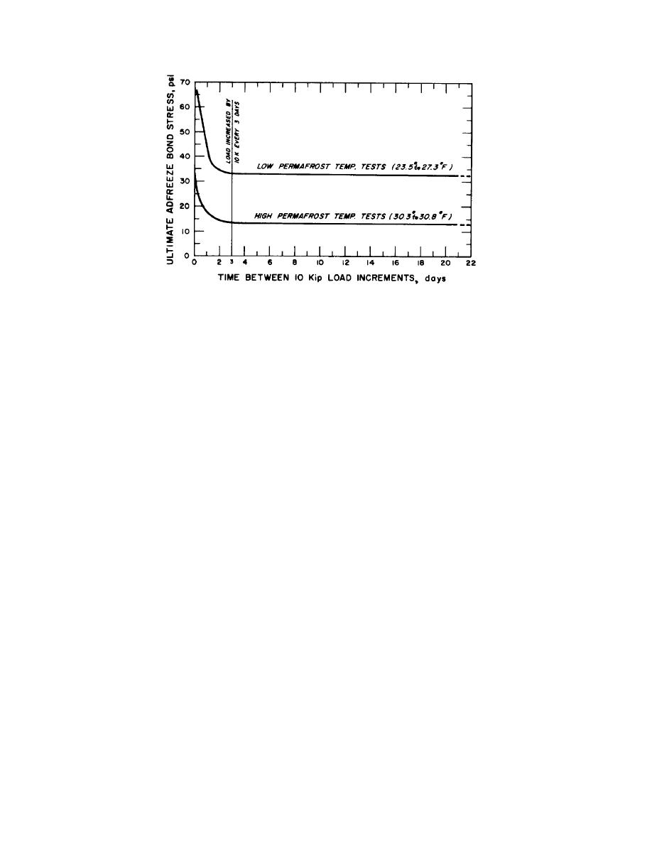
Figure 4-85. Effect of rate of loading and temperature on adfreeze strength of steel pipe piles134. Curves based on tests of
6 inch steel pipe piles installed in augered holes backfilled with silt-water slurry at Fairbanks, Alaska. Embedment of piles
in permafrost varied from 10.9 to 12.0 ft.
were only held one day. However, that obtained in the
made with equivalent end bearing piles. Such analyses
test shown in figure 4-84 with each increment held at
give indications of the length of pile actively supporting
least four days requires no correction. A continuous
load and assist in recognition of failure situations.
record of deformations should be obtained under each
(8) A value of failure or ultimate load
load increment and continuing deformation rates at ends
should be determined from the load test results. A
of the increment periods should be plotted against load
number of common criteria for selection of failure load
5
are listed in TM 5-818-1/AFM 88-3, Chapter 7 . The
to assist in determination of the load level at which
most appropriate of these for tests in frozen ground is
excessive creep deformations begin. However, it should
that which defines the failure or ultimate load as the load
be kept in mind that stress redistribution along the length
indicated by intersection of tangent lines drawn through
of the pile under an increment of load may continue far
the initial, flatter portion of the load-deformation curve
beyond a period of even three days and that such
and through the steeper part of the same curve.
readings should not be assumed to quantitatively
Adjustment to the critical design temperature should then
represent creep rates under long term steady load. The
be made if required, using the data shown in figure 4-82
load may be completely removed at intervals during the
and the allowable design load should be computed by
test and the rebound of the pile noted. The rebound of
application of a factor of safety as indicated in h below.
the pile after the maximum load had been released
(9) If the length of time required to perform
should be observed for at least 24 hours.
The
an exploratory load test as described is unacceptable, an
deformation of the pile after rebound (point E in fig. 4-
alternative approach is to perform simultaneously several
84) is known as the net or plastic deformation. The
verification pile load tests as described below, with load
algebraic difference between the total deformation and
values selected so as to positively bracket and establish
the net settlement (difference in deflection between C
the acceptable design load.
and E in fig. 4-84) is known as the elastic deformation of
(10) In verification pile load tests the pile
the pile and soil. The net or plastic deformation of piles
in permafrost rarely exceeds 0.50 inch before complete
may be loaded to the design load in a single increment
failure of the pile.
and then to 2 1/2 times the design load in a second
(7) As shown in figure 4-84, analysis is
increment, all other requirements remaining the same as
aided by comparing the observed deformations with the
for an ex-
computed pile shortening. Comparison may also be
4-142


 Previous Page
